dan@theluthers.net [KurzList]
2017-11-14 17:49:08 UTC
(okay -- so the message truncation function of Yahoo works...)
This setup allowed me to preserve the standard headers on the fans, and when I tested them prior to installation I promptly blew the fuse. I blew another fuse when trying to read the amp draw. I figured since I was powering the SCSI2SD card with the termination power, I could just install the header in the HDD power connector, so I popped the pins out and installed them in a 4-pin SPOX connector, connected the header and â you guessed it â blew yet another fuse. After all the work I put into mounting this fan I wasnât going to let it go to waste, so I clipped the fan ends and installed a 2-pin SPOX connector on the 40mm fan and the 4-pin connector on the case fan into the HDD power. No more blown fuses.
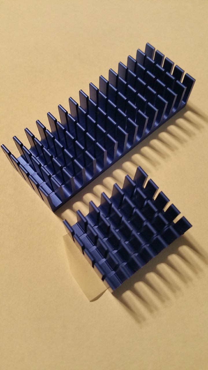
After this system was mostly reassembled, as Iâm running the diagnostics and looking things over I noticed the two 7805 VRMs on the audio board were hot, way too hot. I looked at this as an opportunity for improvement. I first looked at the small TO-220 heat sinks I had around, but even after clipping the support lead it was just too tall for this application, and I had my doubts about the spacing. Then I remembered the set of Thermaltake chipset heatsinks that came with the RAM heat spreaders I bought some years ago, just sitting in a drawer. I pulled one out and at 58mm, they were way too wide for this application, but the 20mm height was just about perfect. I cut it in half:
Loading Image... http://theluthers.net/images/heatsinks.jpg
http://theluthers.net/images/heatsinks.jpg
http://theluthers.net/images/heatsinks.jpg http://theluthers.net/images/heatsinks.jpg
View on theluthers.net http://theluthers.net/images/heatsinks.jpg
Preview by Yahoo
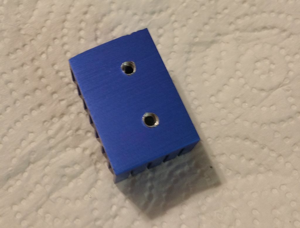
⊠spent several minutes with a product called âGoof-offâ and some paper towels to remove the adhesive. There are two of these per kit, and only one had the adhesive; a fact I wish I had been aware of earlier. I squared the heatsink against the VRMs and marked off the centers of the mounting holes. I then used a nifty little combination drill and tap set, the smallest bit of which was an M3x0.5. An application of penetrating oil and the âthree steps forward, one step backâ tapping process and I had a pair of nice M3 mounting holes in the heat sink.
Loading Image... http://theluthers.net/images/hs-tapped.jpg
http://theluthers.net/images/hs-tapped.jpg
http://theluthers.net/images/hs-tapped.jpg http://theluthers.net/images/hs-tapped.jpg
View on theluthers.net http://theluthers.net/images/hs-tapped.jpg
Preview by Yahoo
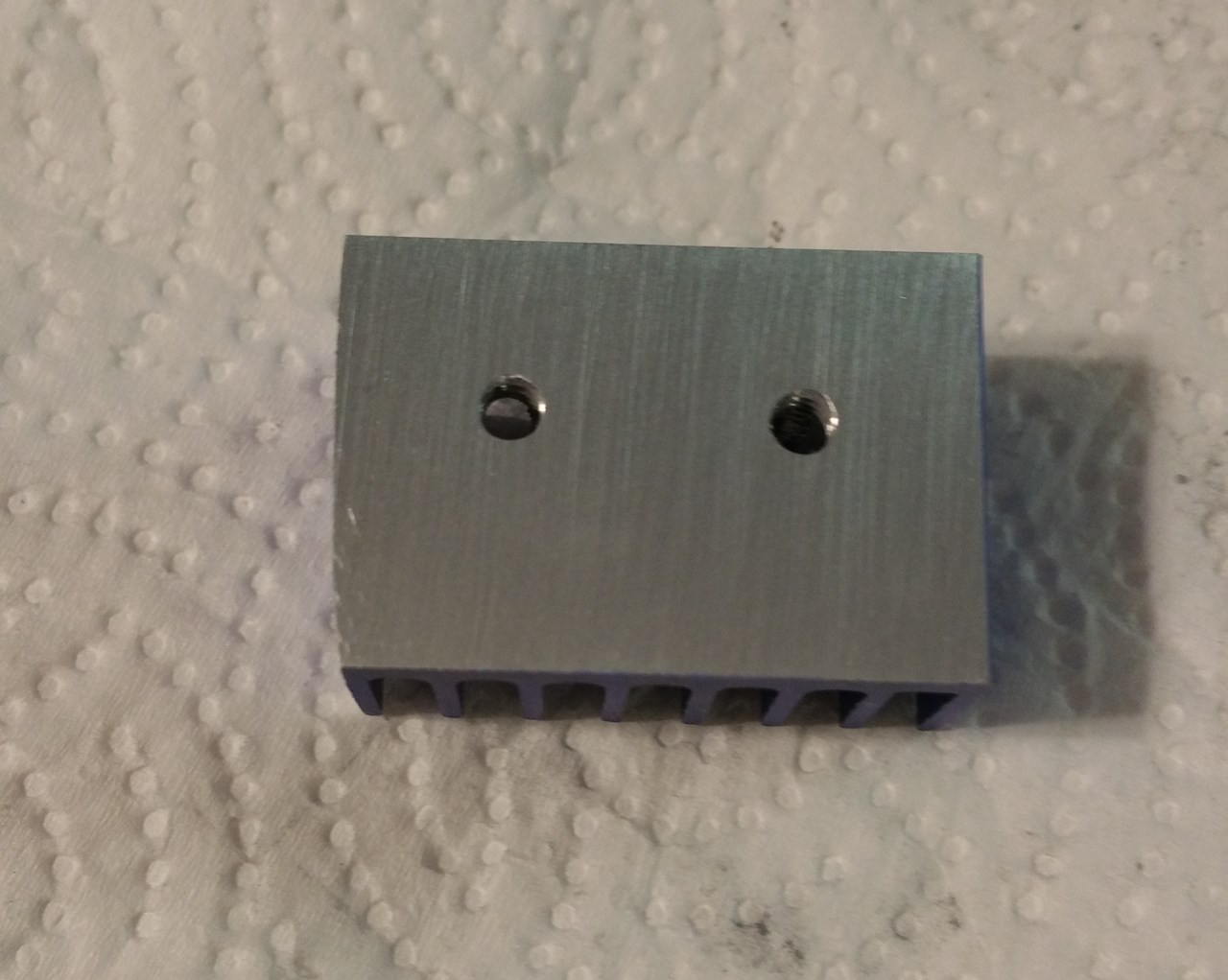
I could have probably left the heatsink as is at this point, perhaps even slightly countersinking the opening for deburring purposes, but if youâre familiar with the application of heatsinks, you know one needs to have as smooth a mating surface as possible for maximum heat transfer. So I used some 440-grit sandpaper (hey, itâs what I had on hand) and smoothed the cut end and hone the surface. I finished this up using a sheet of cheap office paper to produce a surface much better than the original.
Loading Image... http://theluthers.net/images/hs-honed.jpg
http://theluthers.net/images/hs-honed.jpg
http://theluthers.net/images/hs-honed.jpg http://theluthers.net/images/hs-honed.jpg
View on theluthers.net http://theluthers.net/images/hs-honed.jpg
Preview by Yahoo
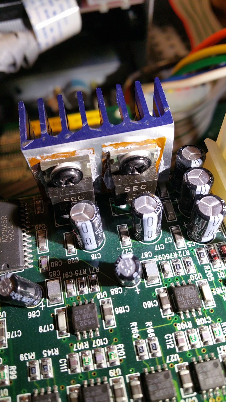
Applying some Noctua NT-H1 thermal paste to the heat sink, using that to hold a mica insulator in place and a dab of the paste on it provides good heat transfer while the mica insures insulation between it and the transistorâs ground. A nylon bushing and M3 screw completed this little operation.
Loading Image... http://theluthers.net/images/hs-installed.jpg
http://theluthers.net/images/hs-installed.jpg
http://theluthers.net/images/hs-installed.jpg http://theluthers.net/images/hs-installed.jpg
View on theluthers.net http://theluthers.net/images/hs-installed.jpg
Preview by Yahoo
And this little project is complete.
Loading Image... http://theluthers.net/images/K2600R-complete.jpg
http://theluthers.net/images/K2600R-complete.jpg
http://theluthers.net/images/K2600R-complete.jpg http://theluthers.net/images/K2600R-complete.jpg
View on theluthers.net http://theluthers.net/images/K2600R-complete.jpg
Preview by Yahoo
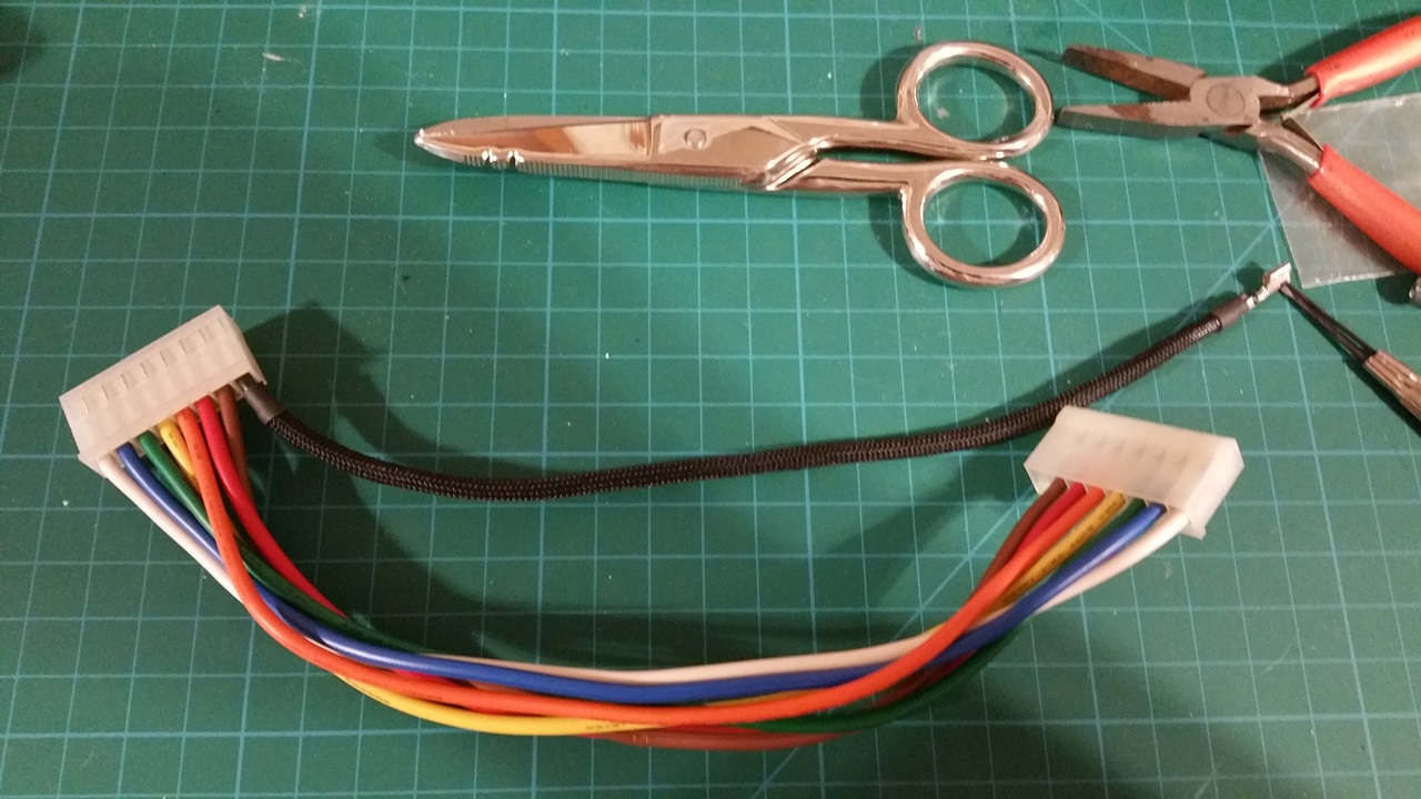
As Iâm buttoning this up, I got the idea Iâd like to try my hand at sleeving the power supply cables in paracord. This came from my research into wrapping the ribbon cables in PET sleeving, and Iâll be completely honest here and say it serves no purpose other than vanity. So I pulled the main power supply cable from the CPU board since it was the only one not twisted and began the process. Using a small common screwdriver, I carefully pried up the plastic tab which allowed the pin to unlock and slide out. I knew I had to coat the pin in something to keep it from snagging the cord, so I used some heat-shrink tubing to cover the pin and allow it to slide down the cord. I cut the paracord to length and removed the nylon cores, then slid the pin into one end. inchworming my way down. Once I had the jacket about halfway on, I slid smaller pieces of heatshrink over it to seal the finished ends after removing the heatshrink cap.
Loading Image... http://theluthers.net/images/pscables-proc.jpg
http://theluthers.net/images/pscables-proc.jpg
http://theluthers.net/images/pscables-proc.jpg http://theluthers.net/images/pscables-proc.jpg
View on theluthers.net http://theluthers.net/images/pscables-proc.jpg
Preview by Yahoo
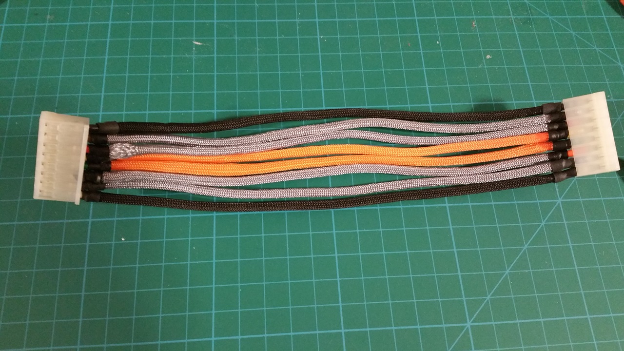
I got lucky with my first two cables. On my third attempt, one end started fraying as I was almost complete. So for the remainder, I used a lighter to melt the ends and the expansion of scissors to expand the opening, a lesson I must not have taken to heart with all the PET sleeving I did earlier.
Loading Image... http://theluthers.net/images/pscables-wrapped.jpg
http://theluthers.net/images/pscables-wrapped.jpg
http://theluthers.net/images/pscables-wrapped.jpg http://theluthers.net/images/pscables-wrapped.jpg
View on theluthers.net http://theluthers.net/images/pscables-wrapped.jpg
Preview by Yahoo
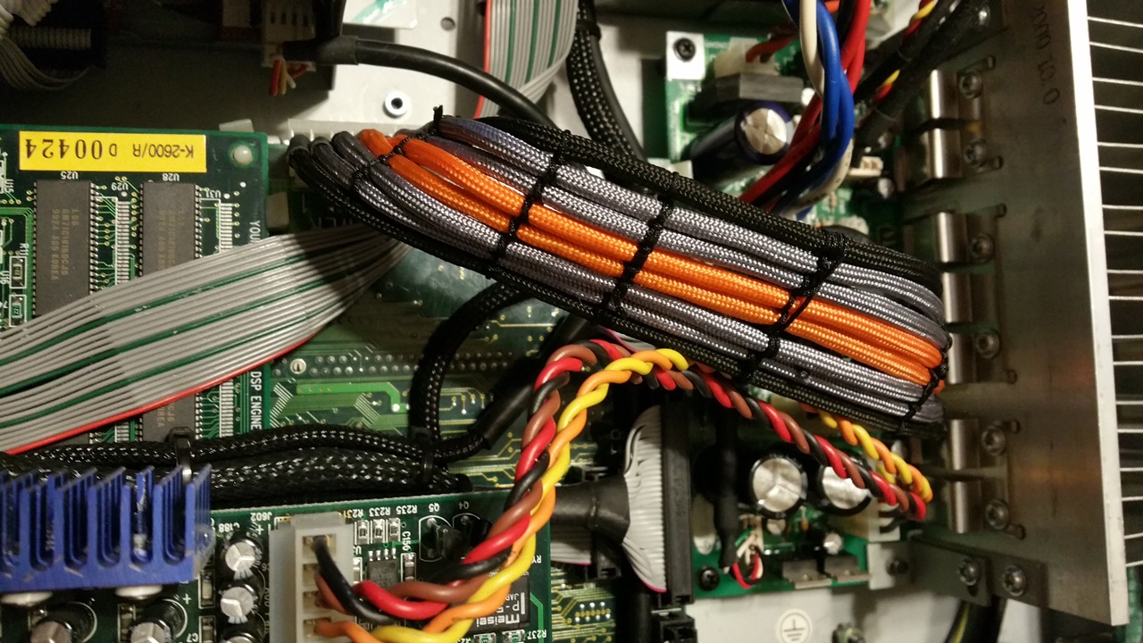
All I had to do was keep them in place, so I used some nylon thread to stitch the cables together at several points along the length, and this little project comes to a close.
Loading Image... http://theluthers.net/images/K2600R-pscables-installed.jpg
http://theluthers.net/images/K2600R-pscables-installed.jpg
http://theluthers.net/images/K2600R-pscables-installed.j... http://theluthers.net/images/K2600R-pscables-installed.jpg
View on theluthers.net http://theluthers.net/images/K2600R-pscables-installed.jpg
Preview by Yahoo
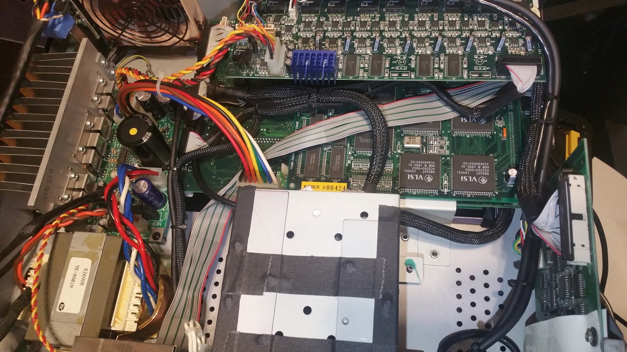
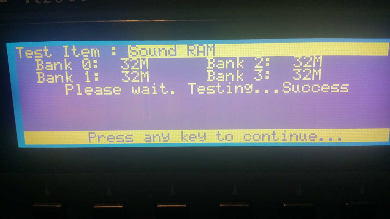
Yeah, I know; this serves no really useful purpose, but I gotta say â it sure looks cool! Now all to do is go through the diagnostics one last time to verify installation and access to the RAM:
Loading Image... http://theluthers.net/images/K2600R-ram.jpg
http://theluthers.net/images/K2600R-ram.jpg
http://theluthers.net/images/K2600R-ram.jpg http://theluthers.net/images/K2600R-ram.jpg
View on theluthers.net http://theluthers.net/images/K2600R-ram.jpg
Preview by Yahoo
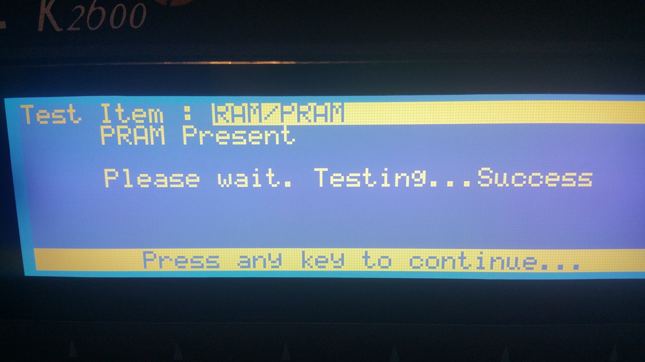
The PRAM:
Loading Image... http://theluthers.net/images/K2600R-pram.jpg
http://theluthers.net/images/K2600R-pram.jpg
http://theluthers.net/images/K2600R-pram.jpg http://theluthers.net/images/K2600R-pram.jpg
View on theluthers.net http://theluthers.net/images/K2600R-pram.jpg
Preview by Yahoo
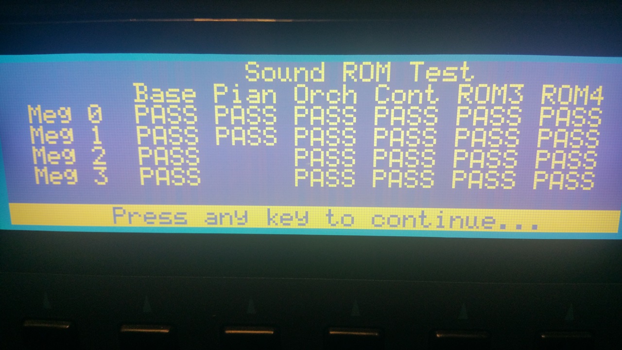
The ROM installation:
Loading Image... http://theluthers.net/images/K2600R-rom.jpg
http://theluthers.net/images/K2600R-rom.jpg
http://theluthers.net/images/K2600R-rom.jpg http://theluthers.net/images/K2600R-rom.jpg
View on theluthers.net http://theluthers.net/images/K2600R-rom.jpg
Preview by Yahoo
And finally access to the SCSI2SD devices:
Loading Image... http://theluthers.net/images/K2600R-scsi.jpg
http://theluthers.net/images/K2600R-scsi.jpg
http://theluthers.net/images/K2600R-scsi.jpg http://theluthers.net/images/K2600R-scsi.jpg
View on theluthers.net http://theluthers.net/images/K2600R-scsi.jpg
Preview by Yahoo
So, after all this, whatâs next? Really, whatâs left is a better question. I wouldnât mind replacing the displays with a white-on-black LED versions. The PSU could stand to have the 220uf C6 capacitor replaced with a 100uf cap, per Kurzweilâs recommendation, and if Iâm in there Iâd probably replace that variable resistor R9 for the +12V adjustment with a 100K precision multi-turn pot.
Having worked on a K2000, a K2500 and now a K2600 series, I can see the progression. All along the K series, Kurzweil built these things like tanks. Some of the things like the volume/headphone board are just common from the K2000 series (says so right on the silkscreen). But other things like the mounting tray for the audio I/O board â itâs about time.
A big shout out to Alex Goetsman â dude, you always do manage to come up with the stuff.
This setup allowed me to preserve the standard headers on the fans, and when I tested them prior to installation I promptly blew the fuse. I blew another fuse when trying to read the amp draw. I figured since I was powering the SCSI2SD card with the termination power, I could just install the header in the HDD power connector, so I popped the pins out and installed them in a 4-pin SPOX connector, connected the header and â you guessed it â blew yet another fuse. After all the work I put into mounting this fan I wasnât going to let it go to waste, so I clipped the fan ends and installed a 2-pin SPOX connector on the 40mm fan and the 4-pin connector on the case fan into the HDD power. No more blown fuses.
After this system was mostly reassembled, as Iâm running the diagnostics and looking things over I noticed the two 7805 VRMs on the audio board were hot, way too hot. I looked at this as an opportunity for improvement. I first looked at the small TO-220 heat sinks I had around, but even after clipping the support lead it was just too tall for this application, and I had my doubts about the spacing. Then I remembered the set of Thermaltake chipset heatsinks that came with the RAM heat spreaders I bought some years ago, just sitting in a drawer. I pulled one out and at 58mm, they were way too wide for this application, but the 20mm height was just about perfect. I cut it in half:
Loading Image...
 http://theluthers.net/images/heatsinks.jpg
http://theluthers.net/images/heatsinks.jpg
http://theluthers.net/images/heatsinks.jpg http://theluthers.net/images/heatsinks.jpg
View on theluthers.net http://theluthers.net/images/heatsinks.jpg
Preview by Yahoo
⊠spent several minutes with a product called âGoof-offâ and some paper towels to remove the adhesive. There are two of these per kit, and only one had the adhesive; a fact I wish I had been aware of earlier. I squared the heatsink against the VRMs and marked off the centers of the mounting holes. I then used a nifty little combination drill and tap set, the smallest bit of which was an M3x0.5. An application of penetrating oil and the âthree steps forward, one step backâ tapping process and I had a pair of nice M3 mounting holes in the heat sink.
Loading Image...
 http://theluthers.net/images/hs-tapped.jpg
http://theluthers.net/images/hs-tapped.jpg
http://theluthers.net/images/hs-tapped.jpg http://theluthers.net/images/hs-tapped.jpg
View on theluthers.net http://theluthers.net/images/hs-tapped.jpg
Preview by Yahoo
I could have probably left the heatsink as is at this point, perhaps even slightly countersinking the opening for deburring purposes, but if youâre familiar with the application of heatsinks, you know one needs to have as smooth a mating surface as possible for maximum heat transfer. So I used some 440-grit sandpaper (hey, itâs what I had on hand) and smoothed the cut end and hone the surface. I finished this up using a sheet of cheap office paper to produce a surface much better than the original.
Loading Image...
 http://theluthers.net/images/hs-honed.jpg
http://theluthers.net/images/hs-honed.jpg
http://theluthers.net/images/hs-honed.jpg http://theluthers.net/images/hs-honed.jpg
View on theluthers.net http://theluthers.net/images/hs-honed.jpg
Preview by Yahoo
Applying some Noctua NT-H1 thermal paste to the heat sink, using that to hold a mica insulator in place and a dab of the paste on it provides good heat transfer while the mica insures insulation between it and the transistorâs ground. A nylon bushing and M3 screw completed this little operation.
Loading Image...
 http://theluthers.net/images/hs-installed.jpg
http://theluthers.net/images/hs-installed.jpg
http://theluthers.net/images/hs-installed.jpg http://theluthers.net/images/hs-installed.jpg
View on theluthers.net http://theluthers.net/images/hs-installed.jpg
Preview by Yahoo
And this little project is complete.
Loading Image...
 http://theluthers.net/images/K2600R-complete.jpg
http://theluthers.net/images/K2600R-complete.jpg
http://theluthers.net/images/K2600R-complete.jpg http://theluthers.net/images/K2600R-complete.jpg
View on theluthers.net http://theluthers.net/images/K2600R-complete.jpg
Preview by Yahoo
As Iâm buttoning this up, I got the idea Iâd like to try my hand at sleeving the power supply cables in paracord. This came from my research into wrapping the ribbon cables in PET sleeving, and Iâll be completely honest here and say it serves no purpose other than vanity. So I pulled the main power supply cable from the CPU board since it was the only one not twisted and began the process. Using a small common screwdriver, I carefully pried up the plastic tab which allowed the pin to unlock and slide out. I knew I had to coat the pin in something to keep it from snagging the cord, so I used some heat-shrink tubing to cover the pin and allow it to slide down the cord. I cut the paracord to length and removed the nylon cores, then slid the pin into one end. inchworming my way down. Once I had the jacket about halfway on, I slid smaller pieces of heatshrink over it to seal the finished ends after removing the heatshrink cap.
Loading Image...
 http://theluthers.net/images/pscables-proc.jpg
http://theluthers.net/images/pscables-proc.jpg
http://theluthers.net/images/pscables-proc.jpg http://theluthers.net/images/pscables-proc.jpg
View on theluthers.net http://theluthers.net/images/pscables-proc.jpg
Preview by Yahoo
I got lucky with my first two cables. On my third attempt, one end started fraying as I was almost complete. So for the remainder, I used a lighter to melt the ends and the expansion of scissors to expand the opening, a lesson I must not have taken to heart with all the PET sleeving I did earlier.
Loading Image...
 http://theluthers.net/images/pscables-wrapped.jpg
http://theluthers.net/images/pscables-wrapped.jpg
http://theluthers.net/images/pscables-wrapped.jpg http://theluthers.net/images/pscables-wrapped.jpg
View on theluthers.net http://theluthers.net/images/pscables-wrapped.jpg
Preview by Yahoo
All I had to do was keep them in place, so I used some nylon thread to stitch the cables together at several points along the length, and this little project comes to a close.
Loading Image...
 http://theluthers.net/images/K2600R-pscables-installed.jpg
http://theluthers.net/images/K2600R-pscables-installed.jpg
http://theluthers.net/images/K2600R-pscables-installed.j... http://theluthers.net/images/K2600R-pscables-installed.jpg
View on theluthers.net http://theluthers.net/images/K2600R-pscables-installed.jpg
Preview by Yahoo
Yeah, I know; this serves no really useful purpose, but I gotta say â it sure looks cool! Now all to do is go through the diagnostics one last time to verify installation and access to the RAM:
Loading Image...
 http://theluthers.net/images/K2600R-ram.jpg
http://theluthers.net/images/K2600R-ram.jpg
http://theluthers.net/images/K2600R-ram.jpg http://theluthers.net/images/K2600R-ram.jpg
View on theluthers.net http://theluthers.net/images/K2600R-ram.jpg
Preview by Yahoo
The PRAM:
Loading Image...
 http://theluthers.net/images/K2600R-pram.jpg
http://theluthers.net/images/K2600R-pram.jpg
http://theluthers.net/images/K2600R-pram.jpg http://theluthers.net/images/K2600R-pram.jpg
View on theluthers.net http://theluthers.net/images/K2600R-pram.jpg
Preview by Yahoo
The ROM installation:
Loading Image...
 http://theluthers.net/images/K2600R-rom.jpg
http://theluthers.net/images/K2600R-rom.jpg
http://theluthers.net/images/K2600R-rom.jpg http://theluthers.net/images/K2600R-rom.jpg
View on theluthers.net http://theluthers.net/images/K2600R-rom.jpg
Preview by Yahoo
And finally access to the SCSI2SD devices:
Loading Image...
 http://theluthers.net/images/K2600R-scsi.jpg
http://theluthers.net/images/K2600R-scsi.jpg
http://theluthers.net/images/K2600R-scsi.jpg http://theluthers.net/images/K2600R-scsi.jpg
View on theluthers.net http://theluthers.net/images/K2600R-scsi.jpg
Preview by Yahoo
So, after all this, whatâs next? Really, whatâs left is a better question. I wouldnât mind replacing the displays with a white-on-black LED versions. The PSU could stand to have the 220uf C6 capacitor replaced with a 100uf cap, per Kurzweilâs recommendation, and if Iâm in there Iâd probably replace that variable resistor R9 for the +12V adjustment with a 100K precision multi-turn pot.
Having worked on a K2000, a K2500 and now a K2600 series, I can see the progression. All along the K series, Kurzweil built these things like tanks. Some of the things like the volume/headphone board are just common from the K2000 series (says so right on the silkscreen). But other things like the mounting tray for the audio I/O board â itâs about time.
A big shout out to Alex Goetsman â dude, you always do manage to come up with the stuff.