vikramjit banerjee tukiguitarman@yahoo.com [KurzList]
2017-11-15 04:51:13 UTC
How about a similar Post about your exploits with the K2500 rack,I would be very interested as to how that turned out since mine is going through open heart surgery for the last five years and yet refuses to make a sound in spite of a new engine board and miscellaneous new parts and new kdfx,hurts really bad ........
Sent from Yahoo Mail on Android
On Wed, Nov 15, 2017 at 7:13 AM, ***@yahoogroups.com<***@yahoogroups.com> wrote: <!--#yiv9070161662 #yiv9070161662ygrp-mkp {border:1px solid #d8d8d8;font-family:Arial;margin:10px 0;padding:0 10px;}#yiv9070161662 #yiv9070161662ygrp-mkp hr {border:1px solid #d8d8d8;}#yiv9070161662 #yiv9070161662ygrp-mkp #yiv9070161662hd {color:#628c2a;font-size:85%;font-weight:700;line-height:122%;margin:10px 0;}#yiv9070161662 #yiv9070161662ygrp-mkp #yiv9070161662ads {margin-bottom:10px;}#yiv9070161662 #yiv9070161662ygrp-mkp .yiv9070161662ad {padding:0 0;}#yiv9070161662 #yiv9070161662ygrp-mkp .yiv9070161662ad p {margin:0;}#yiv9070161662 #yiv9070161662ygrp-mkp .yiv9070161662ad a {color:#0000ff;text-decoration:none;}#yiv9070161662 #yiv9070161662ygrp-sponsor #yiv9070161662ygrp-lc {font-family:Arial;}#yiv9070161662 #yiv9070161662ygrp-sponsor #yiv9070161662ygrp-lc #yiv9070161662hd {margin:10px 0px;font-weight:700;font-size:78%;line-height:122%;}#yiv9070161662 #yiv9070161662ygrp-sponsor #yiv9070161662ygrp-lc .yiv9070161662ad {margin-bottom:10px;padding:0 0;}-->
The Kurzweil Musical Instrument E-mail Discussion List The Kurzweil Musical Instrument E-mail Discussion List Group
4 Messages
Digest #4711 1a My adventures with K2600 rack units by danaluther 1b Re: My adventures with K2600 rack units by "Jerker Lindborg" fairlightcmi 1c Re: My adventures with K2600 rack units by "Matthew Rubenstein" 2 My adventures with K2600 rack units (continued...) by danaluther
Messages
1a
My adventures with K2600 rack units
Tue Nov 14, 2017 9:39 am (PST) . Posted by:
danaluther
This is going to be a long, meandering post; it will probably qualify as a short novel by the time I finish, so if for you âtl;drâ is a thing, please, just mosey along and donât even try. This was a few months in the making, but I wanted to share my adventures with a pair of K2600Rs I purchasedâŠ
I love me some Kurzweil. I started with a K2000R back in the late 1990âs (which I still have), then eventually moved up to a K2500XS with everything but the KDFX option. I decided I have more keyboards than Iâll ever possibly use and that rack mount modules are the way to go, and purchased a K2500RS. I then spent the next several months diagnosing a problem that turned out to be a bad engine board, and the next few years patiently waiting for a good price on a KDFX board.
Iâve watched the K2600R prices hover around the $1,200 mark (when they became available), placing them out of my price range; so when a K2600RS came on sale for around $600, I pounced. A couple months later I came across one without the sampling option for significantly less money, and I pounced again. And this is where the fun startsâŠ
K2600RS (#1) was in great shape. All I had to do was come up with the expansion ROMs, PRAM and memory to populate both systems. I had a set of 128MB of RAM from my previous adventure with my 2500 rack unit that needed the engine board swapped out, which was an earlier revision requiring my 2 64MB DIMMS to be replaced with 4 32MB modules. I also decided Iâd try installing SCSI2SD boards in these systems, so I acquired a couple. During this long Kurzweil ownership/repair/upgrade process I managed to acquire many K2500 parts, including a spare sampling option. I heard the SMP-2X (for the K2600 series) was actually a re-screened SMP-2R (from the K2500 series) and I wanted to install my sampling option and see if it really worked.
So, a brief recap of what I wanted to accomplish:
K2600 #1 needed the SCSI2SD, RAM, PRAM and ROM options installed.
K2600 #2 needed the above plus the sampling option. Also, I wanted to replace the fans in both units with a lower current, silent Noctua fan like I did for my 2500 rack.
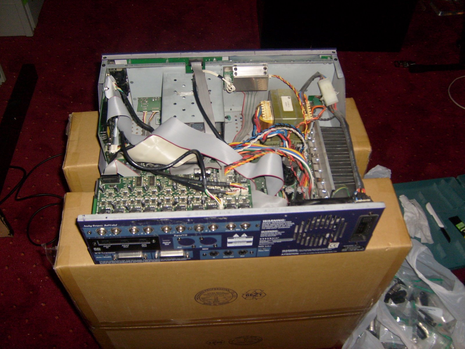
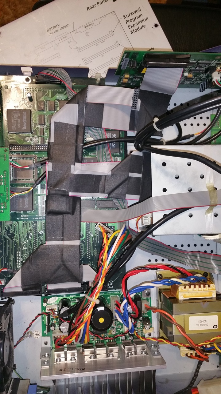
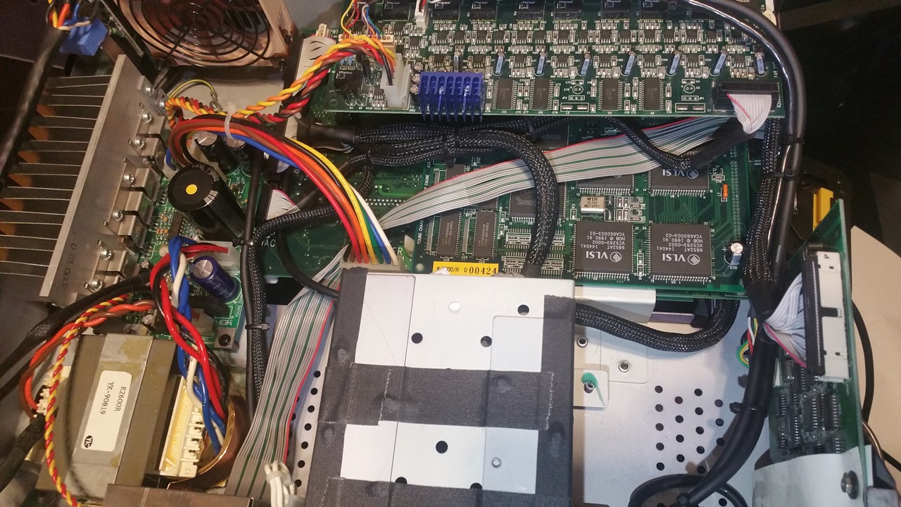
So I opened up the top case of #1 and hereâs where the fun begins. First, it was dirty inside. Second, it seemed like Kurzweil designed the thing to look like a ribbon cable factory exploded inside it!
Loading Image... http://theluthers.net/images/K2600R-pback.jpg
http://theluthers.net/images/K2600R-pback.jpg
http://theluthers.net/images/K2600R-pback.jpg http://theluthers.net/images/K2600R-pback.jpg
View on theluthers.net http://theluthers.net/images/K2600R-pback.jpg
Preview by Yahoo
Sorry for not taking initial pictures; I found these on the internet and itâs what mine looked like when I opened them.
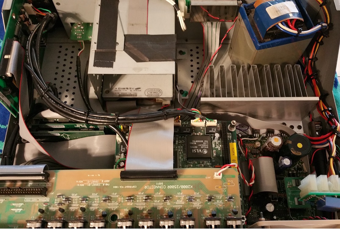
I had some experience with moving cables around in my K2500R with a fairly high degree of success:
Loading Image... http://theluthers.net/images/K2500-after.jpg
http://theluthers.net/images/K2500-after.jpg
http://theluthers.net/images/K2500-after.jpg http://theluthers.net/images/K2500-after.jpg
View on theluthers.net http://theluthers.net/images/K2500-after.jpg
Preview by Yahoo
⊠but the K2600s were a challenge because, as well engineered as these units are (and more on that later), the cable management in these was as tight as it was sloppy, meaning absolutely no slack to fold or bend or route. I suppose I should probably say a little something about myself and history at this point, specifically that I have a more-than-nodding acquaintance with electronic troubleshooting and repair, and that Iâve been building computer systems from components since 1986(-ish). Also, Iâm not a âneat freakâ per-se, but I do have a weird compulsion about keeping my gear tidy and cool where it counts, and upon cracking open the case of these guys, my first thought was âhow does air move around in here?â
With the SCSI2SD cards I bought for about $60 each, I did not purchase any cables figuring I probably had appropriate SCSI cables stashed away in a box of long-forgotten Sun system parts from a previous life. To make a long story short, I did not. But I did have an IEC cable crimper, and itâs not too much of a hardship to search the Amazon and Ebay for a 10 foot length of 50-pin ribbon cable. And I suppose itâs at this point that I decided if Iâm in for a penny I should be in for a pound, and Iâd make up the ribbon cables for the whole system. So I found a sweet deal on a 100-foot roll of 34-pin ribbon cable on Ebay ($15), and started looking for the IEC connectors Iâd need. As it turns out, when buying IEC connectors itâs cheaper to buy a whole box of connectors than it is 4 or 10 of them individually, so a box each of 50, 34, 20 and 16 pin IEC flat ribbon cable connectors was purchased and upon arrival, I promptly opened my own IEC cable shop:
Loading Image... http://theluthers.net/images/cable-making.jpg
http://theluthers.net/images/cable-making.jpg
http://theluthers.net/images/cable-making.jpg http://theluthers.net/images/cable-making.jpg
View on theluthers.net http://theluthers.net/images/cable-making.jpg
Preview by Yahoo
Hereâs a tip for anyone making ribbon cables: a paper cutter with a swing arm is a great tool for making perfectly square cuts in ribbon cable. Thatâs all Iâm sayinâ⊠After all the measuring, cutting, crimping, bending, and folding, I realized the SCSI cable from the underside of the CPU board wasnât ever going to look quite right, so I decided to rip it down the middle and fold it over itself at both connector ends, which made it a nice run from the underside of the board, over and in front of the drive tray.
Loading Image...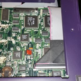 http://theluthers.net/images/K2600RS-scsi-installed.jpg
http://theluthers.net/images/K2600RS-scsi-installed.jpg
http://theluthers.net/images/K2600RS-scsi-installed.jpg http://theluthers.net/images/K2600RS-scsi-installed.jpg
View on theluthers.net http://theluthers.net/images/K2600RS-scsi-installed.jpg
Preview by Yahoo
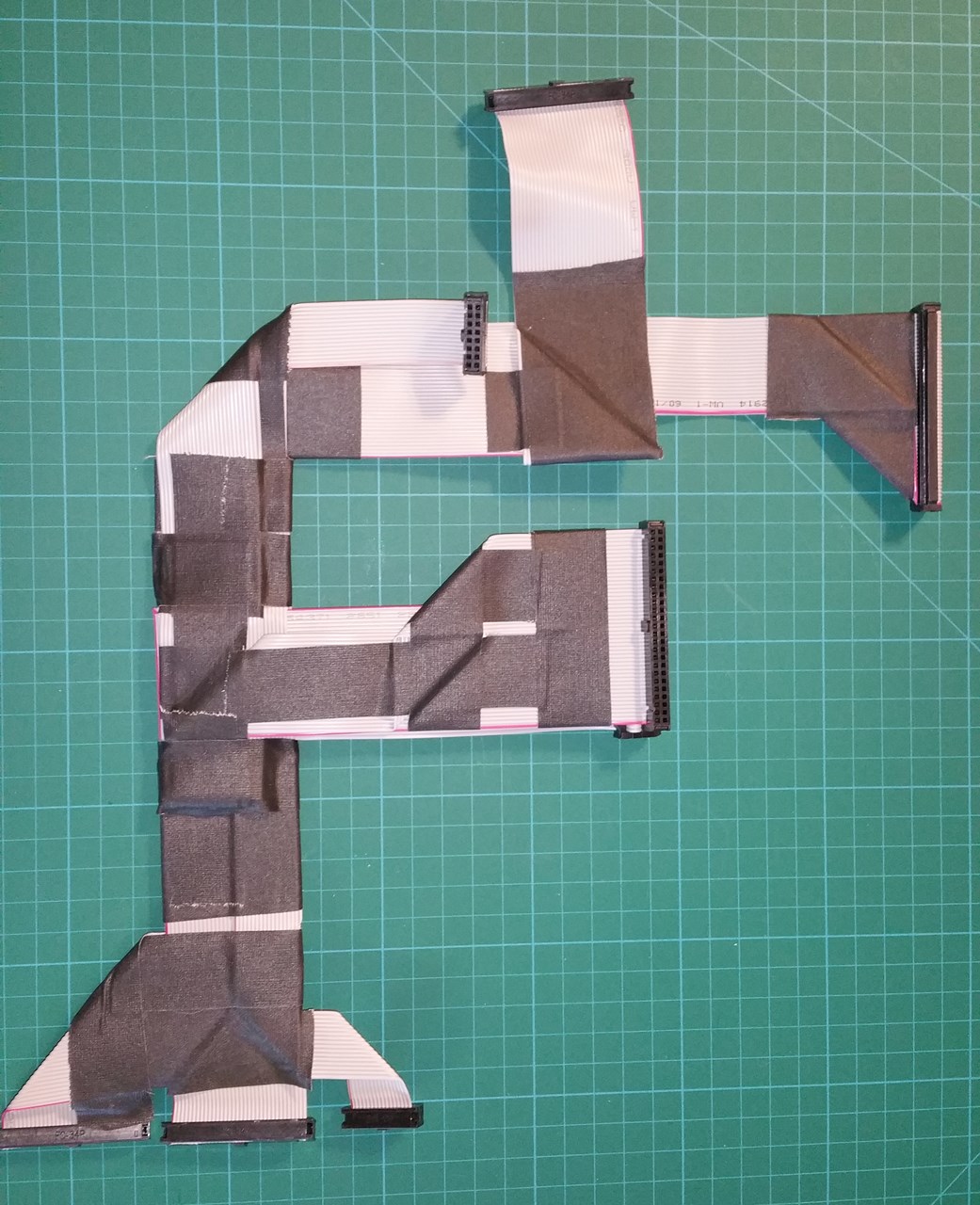
I was also able to take the sampler cable, floppy and DAC connector and layer them all on top of each other, fold them over each other in strategic locations and secure them together with gafferâs tape which made a nice flat-ish custom harness for a K2600R:
Loading Image... http://theluthers.net/images/flat-cable-harness.jpg
http://theluthers.net/images/flat-cable-harness.jpg
http://theluthers.net/images/flat-cable-harness.jpg http://theluthers.net/images/flat-cable-harness.jpg
View on theluthers.net http://theluthers.net/images/flat-cable-harness.jpg
Preview by Yahoo
Upon installation, cable management was fairly complete; the only thing I did not do at this point was replace the scanner board cable since I hadnât purchased any 14-pin connectors, which I did now. The sampler cable was about .5cm too short and the installed cable harness isn't exactly straight, but I was going to just be happy with this attempt.
Loading Image... http://theluthers.net/images/K2600R-flat-installed.jpg
http://theluthers.net/images/K2600R-flat-installed.jpg
http://theluthers.net/images/K2600R-flat-installed.jpg http://theluthers.net/images/K2600R-flat-installed.jpg
View on theluthers.net http://theluthers.net/images/K2600R-flat-installed.jpg
Preview by Yahoo
At this point in time, I purchased a couple metal 3.5 inch SSD mounting trays, mostly because I couldnât find any plastic ones I could use to mount the SCSI2SD cards. Well, thatâs not entirely true; the metal trays were ~$1 each shipped, and the plastic trays I found were going to be around $12 plus shipping, and I deferred to the âless expensiveâ metal trays. These turned out to be a bit of a challenge I overcame by using four 8mm nylon spacers which I epoxied to the tray. Since the SCSI2SD card only has two mounting holes in the back, I figured Iâd have to fill the spacer with epoxy and drill it out for screw holes, but as I was fitting these I found the holes werenât perfectly aligned with my spacers, and the resulting gap would be just wide enough for an M3 screw to burr into the spacer against the cardâs inside mounting hole edge. Problem solved! I discovered the SCSI2SD would draw the necessary power from the on-board SCSI terminator, which saved me from having to manufacture a custom power cable.
Now I got the bright idea that I could replace the floppy drive with a slim version, and use the extra head space on the face plate to mount an LED, SD and micro USB extension cable from the SCSI2SD card; all Iâd need to do was make up a quick jig to clamp across the longest point and adjust a couple blocks to the necessary widths and use my Dremmelâs router attachment with the miniature burring head to cut plastic. And so the side trip begins. I was able to Ebay a couple Teac FD05HG drives for $15 using a âMake Offerâ, and when they came I discovered the floppy connector was a flat FFC 25-pin connector. So I found a couple connector boards with this connector and 34-pin IDC floppy connectors â in China. So I ordered two of them. Iâll just skip to the bottom of the page here and tell you they didnât work. [sigh] More parts for the binâŠ
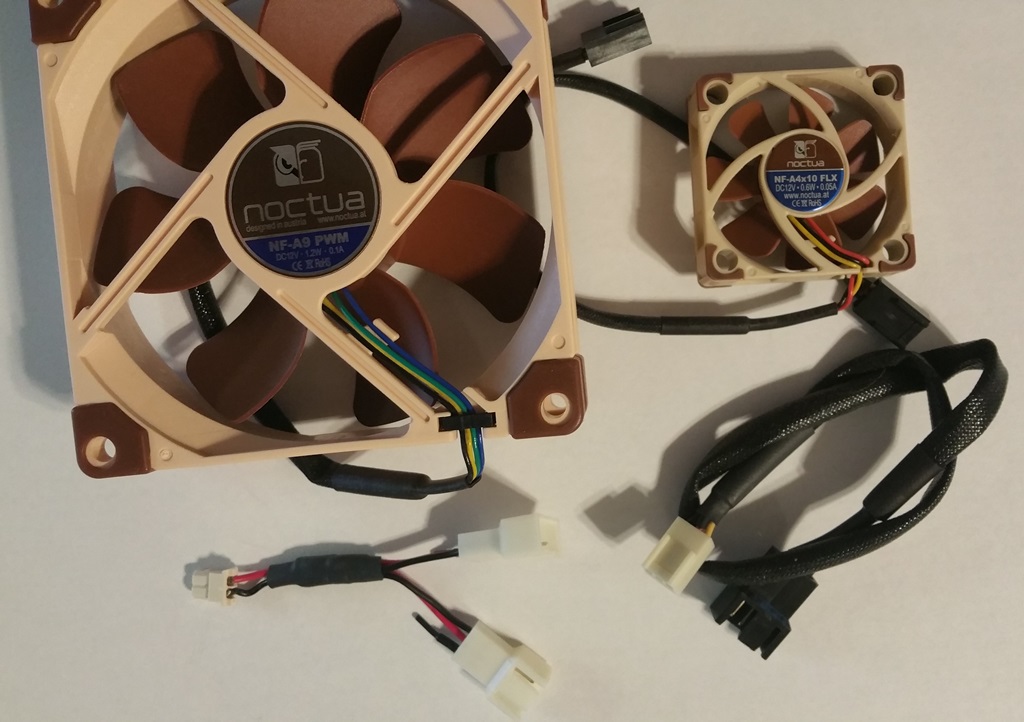
I replaced the stock Panasonic fan with a Noctua NF-A9 PWM. It uses slightly less power than the stock Panasonic Panaflo FBA09A12M (1.2W/0.1A, vs. 2.4W/0.2A - 12V), and the Noctua moves only slightly less air (46.4 cfm vs. 48cfm), but with the internal space opened up allowing air to circulate better through the units, Iâm satisfied the cooling requirements are more than being met. For this installation I simply clipped off the fan lead from the old fan, and repurposed one of the LNA cables in the Noctua kit for its jacketing (nice stuff, that). I carefully slipped a couple pieces of heat-shrink over this to cover the splice ends over the jacketing. Then I clipped off the Noctuaâs terminal, slid down the jacketing enough to slip a couple pieces of tiny heat-shrink tubing and strip the leads, soldered each of the 12V and ground wires together, sealing the PWM leads and individually heat-shrinking all of these wires, then heat-shrinking the connector end and the splice area. I also installed a fan grille over the exposed blades, just for that âextra touch.â The Noctua fans are nearly silent; you really have to put your ear next to one to hear if itâs really on. Many people complain about the noisy Kurzweil fans â I highly recommend this fan over the stock if noise is an issue.
Finally, I installed the ROM, RAM and PRAM, replaced the battery, checked for operation (actually a continuous process, but still), formatted all the SD partitions, updated the OS to 4.11, installed objects for the Orchestral, Contemporary, Dynamic Piano and Vintage Electric ROMS, and enjoyed my well and truly updated K2600RS.
Loading Image...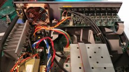 http://theluthers.net/images/K2600R1-finished.jpg
http://theluthers.net/images/K2600R1-finished.jpg
http://theluthers.net/images/K2600R1-finished.jpg http://theluthers.net/images/K2600R1-finished.jpg
View on theluthers.net http://theluthers.net/images/K2600R1-finished.jpg
Preview by Yahoo
Moving on to unit #2âŠ
This was a K2600R, no sampling option. But I had a spare SMP/2K from a box of K2500X parts I picked up at a pretty steep discount (essentially the guts of a K2500X, which I got for spares, you know, âjust in caseâ). I actually purchased this for the sampling option and paid less for the whole box that I would the sampling option, so, bonusâŠ
I should be clear about this point: I really wasnât looking to purchase another K2600 rack. But I still had âKurzweil K2600Râ in my Ebay saved searches, and when it showed up the âBuy it Nowâ price was just too insanely low to pass up. Free shipping to boot, and all the pictures showed a working unit, so I committed.
If I thought unit #1 was dirty inside, unit #2 was just filthy. Giant dust balls everywhere. I even pulled the faceplate from this unit and big dust balls fell out. So, the very first thing I did was remove all the ribbon cables, take it outside and perform a generous cleaning with my air compressor.
I reconnected all the cables and installed a new battery since the startup showed âBattery low (0.0 volts)â, and decided to install the RAM. And this is where things got weird. None of the diagnostics would recognize the new RAM I just bought. So I took the RAM from the other system and installed it, and I got a strange message on the diagnostics, but after a power cycle it too stopped recognizing the RAM. I installed the ânewâ RAM into unit #1, and it recognized everything just fine. At first, I was convinced this was a problem with the CPU board, so I turned to my buddy Alex Goetsman for a replacement, and he came through with one. During the time I was waiting for Alex, I eventually traced this problem to the power supply (no surprise) and fixed the issue, which was a failing capacitor supplying the +5Vdig rail to the CPU board. Now I have an extra CPU board â âjust in caseâ.
I contacted the person from whom I purchased this unit, asking if he had any experiences with it that might shed some light on why the sample memory wouldnât be recognized. It didnât have the blank that goes in the PRAM slot and I figured I must not be the first person with the access panel off. He was such a great guy to communicate with â I wish I could have given him a six-star rating; he had no idea about what the story was, and even though I explicitly said I didnât want a refund and was confident I could repair the unit, he did something I rarely encounter â he refunded me $100. I profusely thanked him, and it greatly offset the cost of the replacement board I purchased from Alex.
I installed my SMP-2K sampler board here, and Iâll be brief: it works. I works just fine. Happy dance. I did tape the panel blanks to the top of the drive bay with gafferâs tape, just in case I ever decide to sell it and someone wants to part it out, the panel blanks will be back in place.
As I was contemplating the cable replacement as I did previously, I thought it might be a good idea to strand and PET sleeve these cables, so I ordered a roll of ÂŒâ, Âœâ, and Ÿâ PET sleeving. As it turns out, all I needed was the ÂŒâ and Âœâ sleeves â these things open up maybe 3-4 times their diameter. So the SCSI, sampler and floppy drive used the Âœâ sleeves, while the DAC and scanner used the ÂŒâ sleeve. And after a dry run, I managed to come up with a pretty good system for making these.
First, cut the cable to length and terminate it on one end. Measure out the PET sleeving against the cable, leaving an inch at each end. When you cut the PET sleeve, use a lighter to seal both ends because this stuff starts fraying quickly, and lightly melting the ends prevents that. I used a good pair of electronics-grade scissors to cut the sleeve, and then stuck the end down each sleeve opening, and opened the scissors to slightly flare them out. Next, I applied a piece of gafferâs tape on one side of the bare end of the ribbon cable, trimming to be exactly the width of the ribbon, which keeps the stranding process from completely separating the cable. With an X-acto knife, I made incisions between every two or three conductors, and separated these to the hilt of the connector down to the tape. Once the ribbon was stranded, I rolled the bare end as tight as I could with the tape inside, then used a small piece of heat-shrink tubing as a cap, shrinking that down to hold it in place. Expanding the PET sleeve and sliding it over the cable is an easy operation with that heat-shrink cap, and once the sleeve was in place, I then cut two 1.5â pieces of heat shrink tubing for the finished ends and slid them down the sleeve. I pulled the sleeve down enough to allow easy working with the termination. Next, I pulled the âcapâ off the rolled-up end and removed the gafferâs tape, smoothing it out to be a straight enough end for applying the connector. Then, I finished the stranding to the connector housing, stretched the PET sleeve to be about an inch from the connectors, moved the heat-shrink pieces into place and heated those to finish the cable.
Rise and repeat.
I also decided the audio connector cables were too short. Which they were; as with the original ribbon cables, the round black cables still had no slack to reroute, and it bothered me just a bit that the two pairs of cables from the headphone/volume and sampler really didnât need to be two cables; with a shielded 8-conductor cable, combining these cables should be doable. The Molex SPOX connectors are tiny, but inexpensive and readily available at Mouser, so I ordered a quantity of 2 through 6 pin SPOX connectors. When they arrived, I discovered they did not include the pins (who does that?!?), so I ordered 100 since that was the minimum quantity â and theyâre only a nickel apiece, so ~$5 for the pinsâŠ
This did not go well at first; these pins are tiny. After a few hours of trying to crimp these micro-pins with an appropriately small pair of needle-nose pliers, I got right well frustrated and ordered a crimper that had a small 28-30 AWG size. And I proceeded to destroy about $2 worth of pins before I discovered the crimper has a flared end I was reversing, causing the pin crimps to shear off the wires when actually crimpingâŠ
I purchased several feet of 8-conductor Mogami 2789 26AWG wire from Redco audio. I decided the two digital I/O board wires to the sampler, and the volume/headphone wires would each be combined into a single cable, and Iâd replace the scanner power cable, but use Mogami W2948 MIDI cable for this application which was 25AWG, better for power cables; that and I already had I discovered the headphone/volume board didnât use the SPOX connectors, but rather had soldered headers into the board, so I unsoldered those and soldered the wires directly into the holes. And after making up all the cables and installing them, testing the unit for operation, I was able to route and zip-tie all the cables, tuck alongside the edges and down the side of the drive bay.
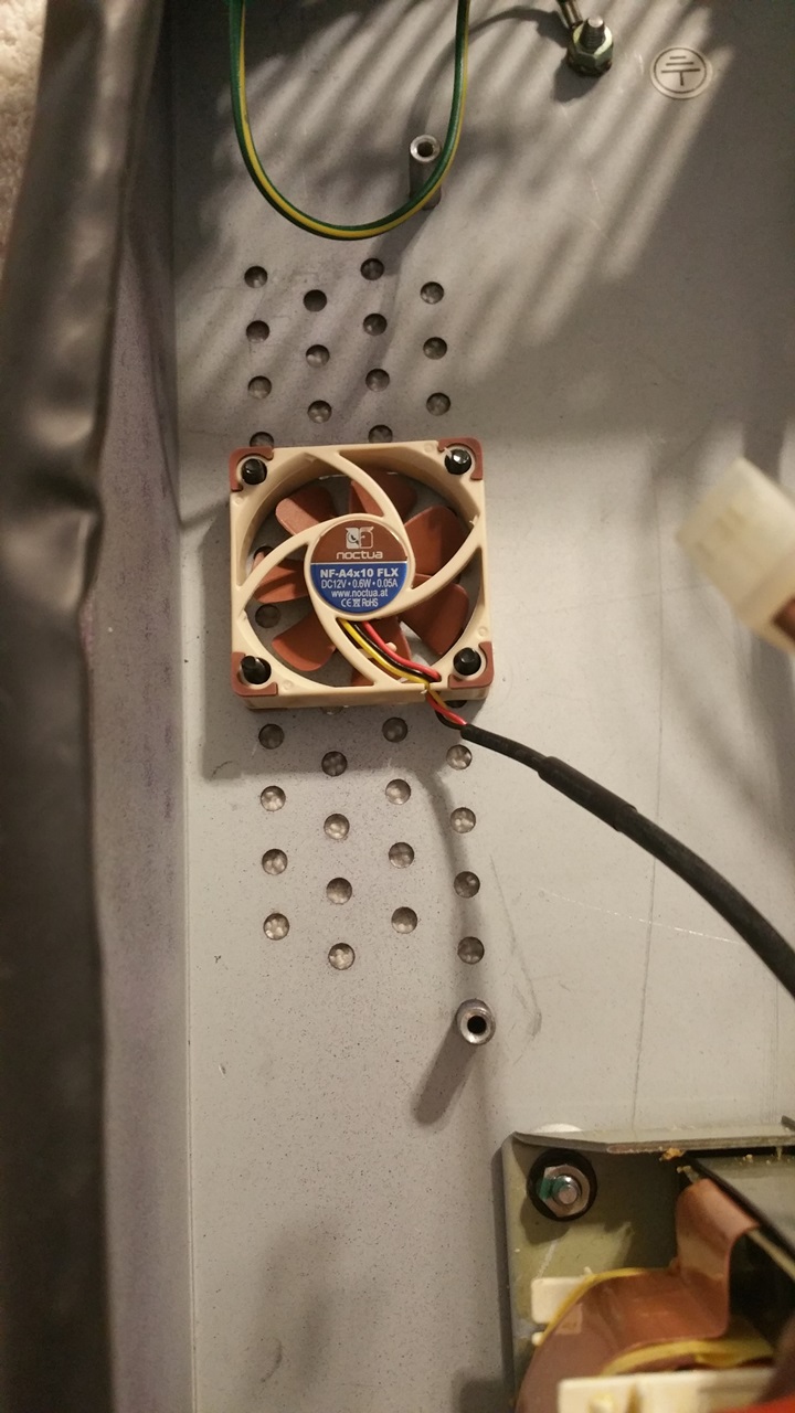
When replacing the stock case fan with the Noctua, I noticed during the course of all this that the power supply was really hot, and decided to try and help that along by installing a little 40x10mm Noctua fan.
The 40mm fan did require me to drill into the case for two mounting holes that were offset by the diameter of the original holes. Gaffer's tape applied to both sides keeps the metal shavings from any kind of infiltration, and deburring and cleanup with the remainder of tape after removing it gets those pesky metal shavings. Mounting with M3 screws, washers and nuts looks nice:
Loading Image...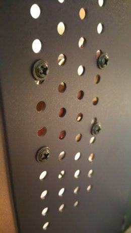 http://theluthers.net/images/K2600R-40fanmount.jpg
http://theluthers.net/images/K2600R-40fanmount.jpg
http://theluthers.net/images/K2600R-40fanmount.jpg http://theluthers.net/images/K2600R-40fanmount.jpg
View on theluthers.net http://theluthers.net/images/K2600R-40fanmount.jpg
Preview by Yahoo
Loading Image... http://theluthers.net/images/K2600R-40faninside.jpg
http://theluthers.net/images/K2600R-40faninside.jpg
http://theluthers.net/images/K2600R-40faninside.jpg http://theluthers.net/images/K2600R-40faninside.jpg
View on theluthers.net http://theluthers.net/images/K2600R-40faninside.jpg
Preview by Yahoo
Some quick calculation showed Iâd be pulling 0.15A combining both fans, which should be below the requirements of the original Panaflo case fan. So I created a two-outlet header attached to a 2-pin SPOX connector:
Loading Image...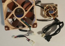 http://theluthers.net/images/Noctua-header.jpg
http://theluthers.net/images/Noctua-header.jpg
http://theluthers.net/images/Noctua-header.jpg http://theluthers.net/images/Noctua-header.jpg
View on theluthers.net http://theluthers.net/images/Noctua-header.jpg
Preview by Yahoo
This setup allowed me to preserve the standard headers on the fans, and when I tested them prior to installation I promptly blew the fuse. I blew another fuse when trying to read the amp draw. I figured since I was powering the SCSI2SD card with the termination power, I could just install the header in the HDD power connector, so I popped the pins out and installed them in a 4-pin SPOX connector, connected the header and â you guessed it â blew yet another fuse. After all the work I put into mounting this fan I wasnât going to let it go to waste, so I clipped the fan ends and installed a 2-pin SPOX connector on the 40mm fan and the 4-pin connector on the case fan into the HDD power. No more blown fuses.
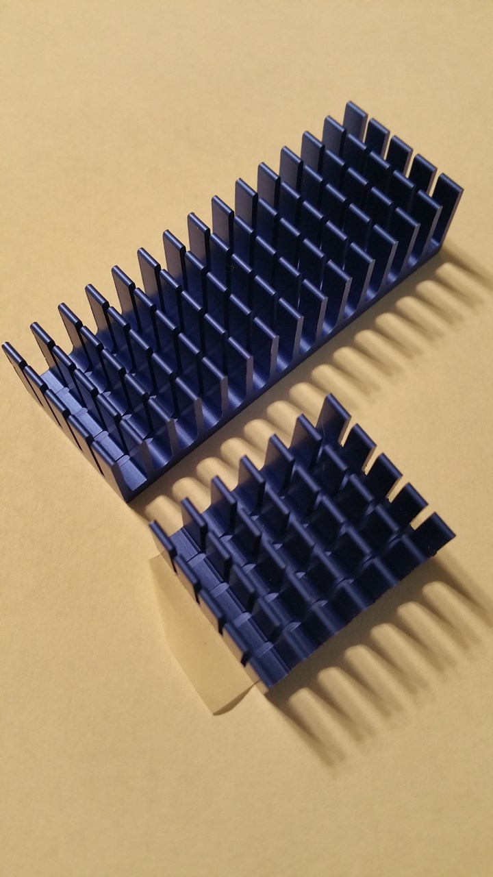
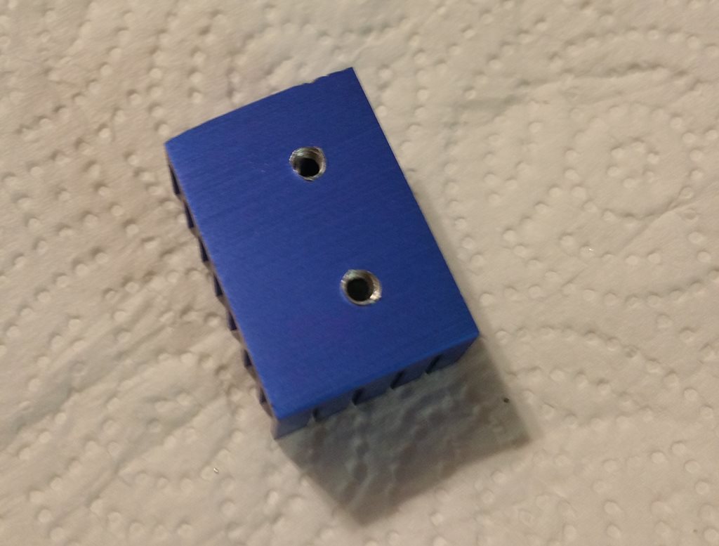
After this system was mostly reassembled, as Iâm running the diagnostics and looking things over I noticed the two 7805 VRMs on the audio board were hot, way too hot. I looked at this as an opportunity for improvement. I first looked at the small TO-220 heat sinks I had around, but even after clipping the support lead it was just too tall for this application, and I had my doubts about the spacing. Then I remembered the set of Thermaltake chipset heatsinks that came with the RAM heat spreaders I bought some years ago, just sitting in a drawer. I pulled one out and at 58mm, they were way too wide for this application, but the 20mm height was just about perfect. I cut it in half:
Loading Image... http://theluthers.net/images/heatsinks.jpg
http://theluthers.net/images/heatsinks.jpg
http://theluthers.net/images/heatsinks.jpg http://theluthers.net/images/heatsinks.jpg
View on theluthers.net http://theluthers.net/images/heatsinks.jpg
Preview by Yahoo
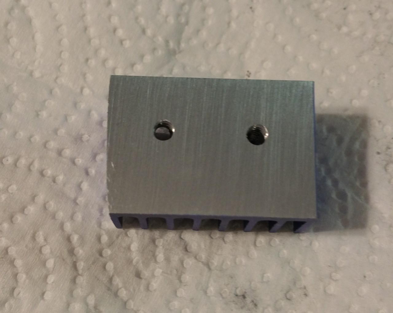
⊠spent several minutes with a product called âGoof-offâ and some paper towels to remove the adhesive. There are two of these per kit, and only one had the adhesive; a fact I wish I had been aware of earlier. I squared the heatsink against the VRMs and marked off the centers of the mounting holes. I then used a nifty little combination drill and tap set, the smallest bit of which was an M3x0.5. An application of penetrating oil and the âthree steps forward, one step backâ tapping process and I had a pair of nice M3 mounting holes in the heat sink.
Loading Image... http://theluthers.net/images/hs-tapped.jpg
http://theluthers.net/images/hs-tapped.jpg
http://theluthers.net/images/hs-tapped.jpg http://theluthers.net/images/hs-tapped.jpg
View on theluthers.net http://theluthers.net/images/hs-tapped.jpg
Preview by Yahoo
I could have probably left the heatsink as is at this point, perhaps even slightly countersinking the opening for deburring purposes, but if youâre familiar with the application of heatsinks, you know one needs to have as smooth a mating surface as possible for maximum heat transfer. So I used some 440-grit sandpaper (hey, itâs what I had on hand) and smoothed the cut end and hone the surface. I finished this up using a sheet of cheap office paper to produce a surface much better than the original.
Loading Image... http://theluthers.net/images/hs-honed.jpg
http://theluthers.net/images/hs-honed.jpg
http://theluthers.net/images/hs-honed.jpg http://theluthers.net/images/hs-honed.jpg
View on theluthers.net http://theluthers.net/images/hs-honed.jpg
Preview by Yahoo
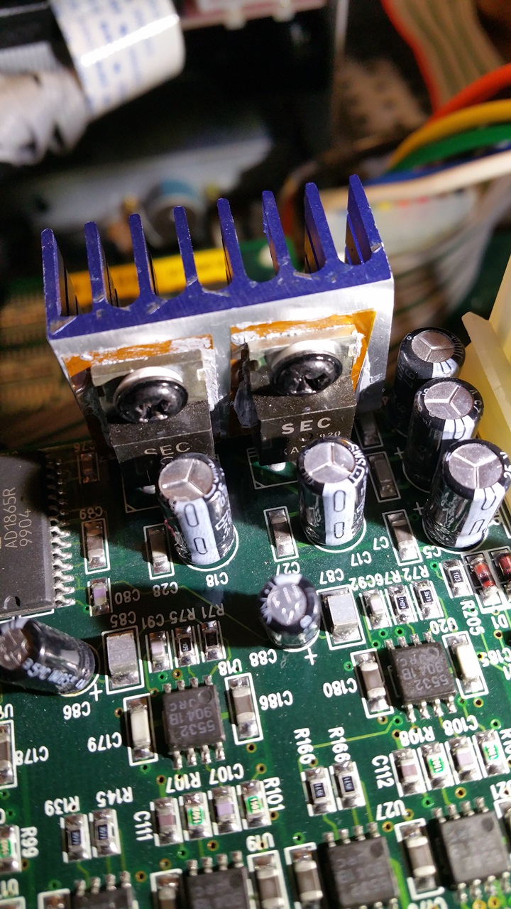
Applying some Noctua NT-H1 thermal paste to the heat sink, using that to hold a mica insulator in place and a dab of the paste on it provides good heat transfer while the mica insures insulation between it and the transistorâs ground. A nylon bushing and M3 screw completed this little operation.
Loading Image... http://theluthers.net/images/hs-installed.jpg
http://theluthers.net/images/hs-installed.jpg
http://theluthers.net/images/hs-installed.jpg http://theluthers.net/images/hs-installed.jpg
View on theluthers.net http://theluthers.net/images/hs-installed.jpg
Preview by Yahoo
And the K2600R is complete:
Loading Image... http://theluthers.net/images/K2600R-complete.jpg
http://theluthers.net/images/K2600R-complete.jpg
http://theluthers.net/images/K2600R-complete.jpg http://theluthers.net/images/K2600R-complete.jpg
View on theluthers.net http://theluthers.net/images/K2600R-complete.jpg
Preview by Yahoo
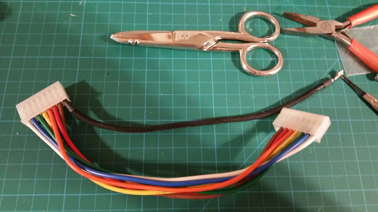
As Iâm buttoning this up, I got the idea Iâd like to try my hand at sleeving the power supply cables in paracord. This came from my research into wrapping the ribbon cables in PET sleeving, and Iâll be completely honest here and say it serves no purpose other than vanity. So I pulled the main power supply cable from the CPU board since it was the only one not twisted and began the process. Using a small common screwdriver, I carefully pried up the plastic tab which allowed the pin to unlock and slide out. I knew I had to coat the pin in something to keep it from snagging the cord, so I used some heat-shrink tubing to cover the pin and allow it to slide down the cord. I cut the paracord to length and removed the nylon cores, then slid the pin into one end. inchworming my way down. Once I had the jacket about halfway on, I slid smaller pieces of heatshrink over it to seal the finished ends after removing the heatshrink cap.
Loading Image... http://theluthers.net/images/pscables-proc.jpg
http://theluthers.net/images/pscables-proc.jpg
http://theluthers.net/images/pscables-proc.jpg http://theluthers.net/images/pscables-proc.jpg
View on theluthers.net http://theluthers.net/images/pscables-proc.jpg
Preview by Yahoo
I got lucky with my first two cables. On my third attempt, one end started fraying as I was almost complete. So for the remainder, I used a lighter to melt the ends and the expansion of scissors to expand the opening, a lesson I must not have taken to heart with all the PET sleeving I did earlier.
Loading Image...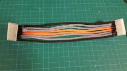 http://theluthers.net/images/pscables-wrapped.jpg
http://theluthers.net/images/pscables-wrapped.jpg
http://theluthers.net/images/pscables-wrapped.jpg http://theluthers.net/images/pscables-wrapped.jpg
View on theluthers.net http://theluthers.net/images/pscables-wrapped.jpg
Preview by Yahoo
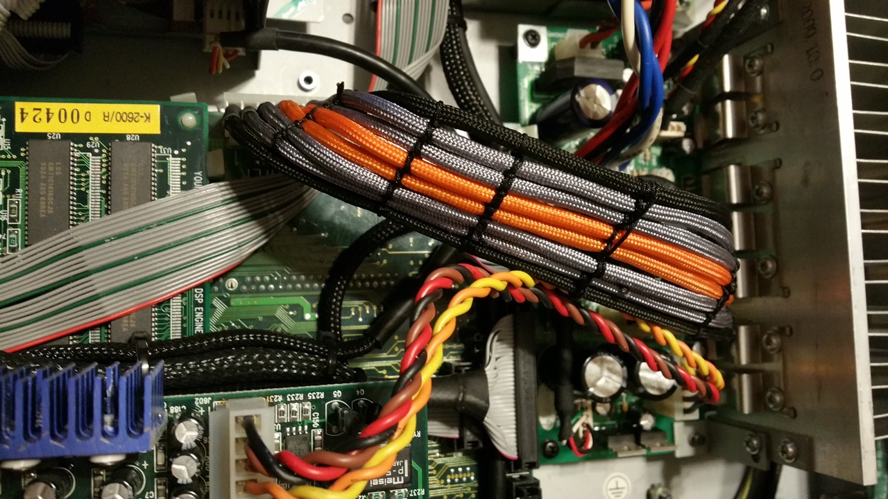
All I had to do was keep them in place, so I used some nylon thread to stitch the cables together at several points along the length, and this little project comes to a close.
Loading Image... http://theluthers.net/images/K2600R-pscables-installed.jpg
http://theluthers.net/images/K2600R-pscables-installed.jpg
http://theluthers.net/images/K2600R-pscables-installed.j... http://theluthers.net/images/K2600R-pscables-installed.jpg
View on theluthers.net http://theluthers.net/images/K2600R-pscables-installed.jpg
Preview by Yahoo
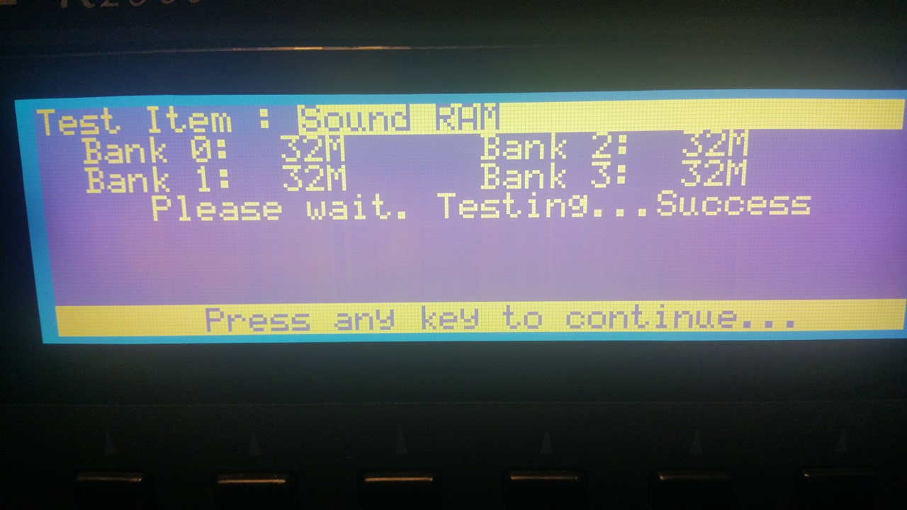
Yeah, I know; this serves no really useful purpose, but I gotta say â it sure looks cool! Now all to do is go through the diagnostics one last time to verify installation and access to the RAM:
Loading Image... http://theluthers.net/images/K2600R-ram.jpg
http://theluthers.net/images/K2600R-ram.jpg
http://theluthers.net/images/K2600R-ram.jpg http://theluthers.net/images/K2600R-ram.jpg
View on theluthers.net http://theluthers.net/images/K2600R-ram.jpg
Preview by Yahoo
The PRAM:
Loading Image...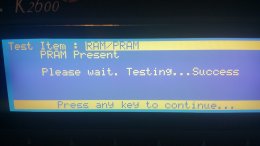 http://theluthers.net/images/K2600R-pram.jpg
http://theluthers.net/images/K2600R-pram.jpg
http://theluthers.net/images/K2600R-pram.jpg http://theluthers.net/images/K2600R-pram.jpg
View on theluthers.net http://theluthers.net/images/K2600R-pram.jpg
Preview by Yahoo
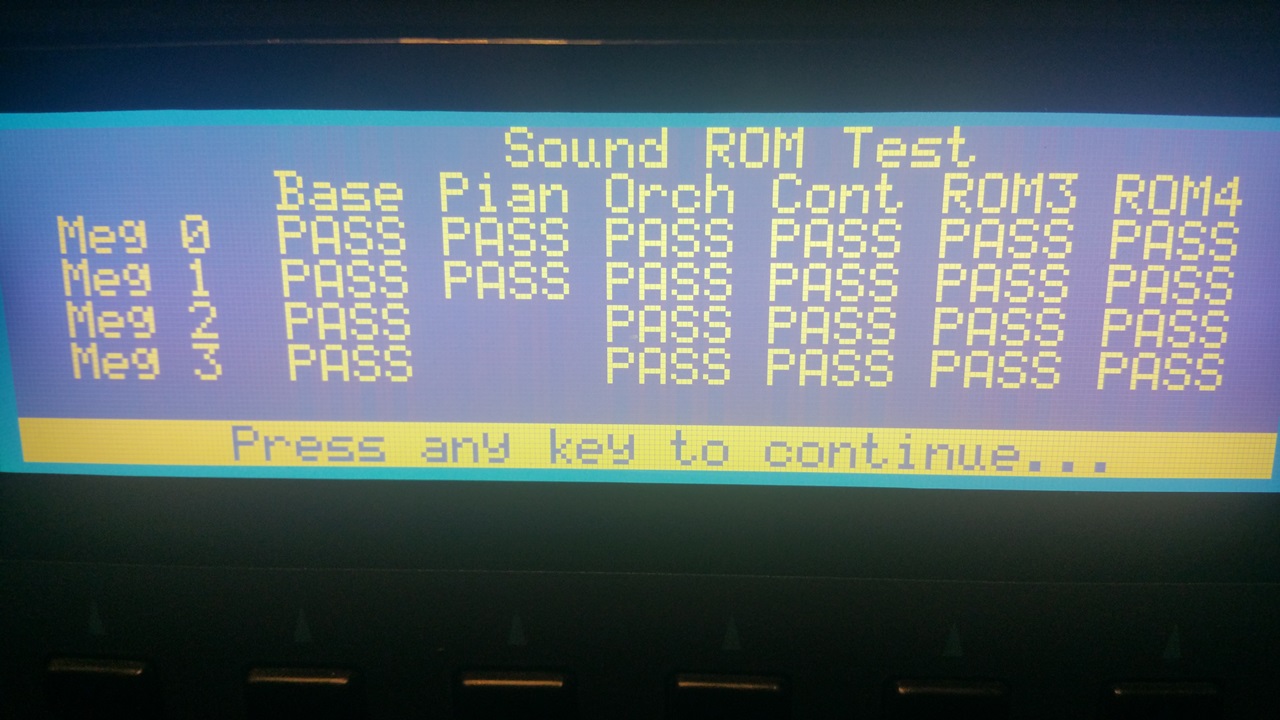
The ROM installation:
Loading Image...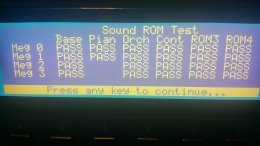 http://theluthers.net/images/K2600R-rom.jpg
http://theluthers.net/images/K2600R-rom.jpg
http://theluthers.net/images/K2600R-rom.jpg http://theluthers.net/images/K2600R-rom.jpg
View on theluthers.net http://theluthers.net/images/K2600R-rom.jpg
Preview by Yahoo
And finally access to the SCSI2SD devices:
Loading Image... http://theluthers.net/images/K2600R-scsi.jpg
http://theluthers.net/images/K2600R-scsi.jpg
http://theluthers.net/images/K2600R-scsi.jpg http://theluthers.net/images/K2600R-scsi.jpg
View on theluthers.net http://theluthers.net/images/K2600R-scsi.jpg
Preview by Yahoo
So, after all this, whatâs next? Really, whatâs left is a better question. I wouldnât mind replacing the displays with a white-on-black LED versions. The PSU could stand to have the 220uf C6 capacitor replaced with a 100uf cap, per Kurzweilâs recommendation, and if Iâm in there Iâd probably replace that variable resistor R9 for the +12V adjustment with a 100K precision multi-turn pot.
Having worked on a K2000, a K2500 and now a K2600 series, I can see the progression. All along the K series, Kurzweil built these things like tanks. Some of the things like the volume/headphone board are just common from the K2000 series (says so right on the silkscreen). But other things like the mounting tray for the audio I/O board â itâs about time.
Big shout out to Alex Gotesman -- dude, you always come through.
Reply to sender . Reply to group . Reply via Web Post . All Messages (3) . Top ^
1b
Re: My adventures with K2600 rack units
Tue Nov 14, 2017 10:04 am (PST) . Posted by:
"Jerker Lindborg" fairlightcmi
Great work!
I can also vouch for Noctua fans as I have done that to my K2500S and K2600XS.
Cheers
Skickat från min iPhone
1c
Re: My adventures with K2600 rack units
Tue Nov 14, 2017 11:05 am (PST) . Posted by:
"Matthew Rubenstein"
Congratulations on publishing your novel :).
Is there anything interesting you're doing with the pair of
K2600RS units working togther as a single rig?
On Tue, 2017-11-14 at 19:04 +0100, Jerker Lindborg
2
My adventures with K2600 rack units (continued...)
Tue Nov 14, 2017 9:49 am (PST) . Posted by:
danaluther
(okay -- so the message truncation function of Yahoo works...)
This setup allowed me to preserve the standard headers on the fans, and when I tested them prior to installation I promptly blew the fuse. I blew another fuse when trying to read the amp draw. I figured since I was powering the SCSI2SD card with the termination power, I could just install the header in the HDD power connector, so I popped the pins out and installed them in a 4-pin SPOX connector, connected the header and â you guessed it â blew yet another fuse. After all the work I put into mounting this fan I wasnât going to let it go to waste, so I clipped the fan ends and installed a 2-pin SPOX connector on the 40mm fan and the 4-pin connector on the case fan into the HDD power. No more blown fuses.
After this system was mostly reassembled, as Iâm running the diagnostics and looking things over I noticed the two 7805 VRMs on the audio board were hot, way too hot. I looked at this as an opportunity for improvement. I first looked at the small TO-220 heat sinks I had around, but even after clipping the support lead it was just too tall for this application, and I had my doubts about the spacing. Then I remembered the set of Thermaltake chipset heatsinks that came with the RAM heat spreaders I bought some years ago, just sitting in a drawer. I pulled one out and at 58mm, they were way too wide for this application, but the 20mm height was just about perfect. I cut it in half:
http://theluthers.net/images/heatsinks.jpg http://theluthers.net/images/heatsinks.jpg
http://theluthers.net/images/heatsinks.jpg
http://theluthers.net/images/heatsinks.jpg http://theluthers.net/images/heatsinks.jpg
View on theluthers.net http://theluthers.net/images/heatsinks.jpg
Preview by Yahoo
⊠spent several minutes with a product called âGoof-offâ and some paper towels to remove the adhesive. There are two of these per kit, and only one had the adhesive; a fact I wish I had been aware of earlier. I squared the heatsink against the VRMs and marked off the centers of the mounting holes. I then used a nifty little combination drill and tap set, the smallest bit of which was an M3x0.5. An application of penetrating oil and the âthree steps forward, one step backâ tapping process and I had a pair of nice M3 mounting holes in the heat sink.
http://theluthers.net/images/hs-tapped.jpg http://theluthers.net/images/hs-tapped.jpg
http://theluthers.net/images/hs-tapped.jpg
http://theluthers.net/images/hs-tapped.jpg http://theluthers.net/images/hs-tapped.jpg
View on theluthers.net http://theluthers.net/images/hs-tapped.jpg
Preview by Yahoo
I could have probably left the heatsink as is at this point, perhaps even slightly countersinking the opening for deburring purposes, but if youâre familiar with the application of heatsinks, you know one needs to have as smooth a mating surface as possible for maximum heat transfer. So I used some 440-grit sandpaper (hey, itâs what I had on hand) and smoothed the cut end and hone the surface. I finished this up using a sheet of cheap office paper to produce a surface much better than the original.
http://theluthers.net/images/hs-honed.jpg http://theluthers.net/images/hs-honed.jpg
http://theluthers.net/images/hs-honed.jpg
http://theluthers.net/images/hs-honed.jpg http://theluthers.net/images/hs-honed.jpg
View on theluthers.net http://theluthers.net/images/hs-honed.jpg
Preview by Yahoo
Applying some Noctua NT-H1 thermal paste to the heat sink, using that to hold a mica insulator in place and a dab of the paste on it provides good heat transfer while the mica insures insulation between it and the transistorâs ground. A nylon bushing and M3 screw completed this little operation.
http://theluthers.net/images/hs-installed.jpg http://theluthers.net/images/hs-installed.jpg
http://theluthers.net/images/hs-installed.jpg
http://theluthers.net/images/hs-installed.jpg http://theluthers.net/images/hs-installed.jpg
View on theluthers.net http://theluthers.net/images/hs-installed.jpg
Preview by Yahoo
And this little project is complete.
http://theluthers.net/images/K2600R-complete.jpg http://theluthers.net/images/K2600R-complete.jpg
http://theluthers.net/images/K2600R-complete.jpg
http://theluthers.net/images/K2600R-complete.jpg http://theluthers.net/images/K2600R-complete.jpg
View on theluthers.net http://theluthers.net/images/K2600R-complete.jpg
Preview by Yahoo
As Iâm buttoning this up, I got the idea Iâd like to try my hand at sleeving the power supply cables in paracord. This came from my research into wrapping the ribbon cables in PET sleeving, and Iâll be completely honest here and say it serves no purpose other than vanity. So I pulled the main power supply cable from the CPU board since it was the only one not twisted and began the process. Using a small common screwdriver, I carefully pried up the plastic tab which allowed the pin to unlock and slide out. I knew I had to coat the pin in something to keep it from snagging the cord, so I used some heat-shrink tubing to cover the pin and allow it to slide down the cord. I cut the paracord to length and removed the nylon cores, then slid the pin into one end. inchworming my way down. Once I had the jacket about halfway on, I slid smaller pieces of heatshrink over it to seal the finished ends after removing the heatshrink cap.
http://theluthers.net/images/pscables-proc.jpg http://theluthers.net/images/pscables-proc.jpg
http://theluthers.net/images/pscables-proc.jpg
http://theluthers.net/images/pscables-proc.jpg http://theluthers.net/images/pscables-proc.jpg
View on theluthers.net http://theluthers.net/images/pscables-proc.jpg
Preview by Yahoo
I got lucky with my first two cables. On my third attempt, one end started fraying as I was almost complete. So for the remainder, I used a lighter to melt the ends and the expansion of scissors to expand the opening, a lesson I must not have taken to heart with all the PET sleeving I did earlier.
http://theluthers.net/images/pscables-wrapped.jpg http://theluthers.net/images/pscables-wrapped.jpg
http://theluthers.net/images/pscables-wrapped.jpg
http://theluthers.net/images/pscables-wrapped.jpg http://theluthers.net/images/pscables-wrapped.jpg
View on theluthers.net http://theluthers.net/images/pscables-wrapped.jpg
Preview by Yahoo
All I had to do was keep them in place, so I used some nylon thread to stitch the cables together at several points along the length, and this little project comes to a close.
http://theluthers.net/images/K2600R-pscables-installed.jpg http://theluthers.net/images/K2600R-pscables-installed.jpg
http://theluthers.net/images/K2600R-pscables-installed.jpg
http://theluthers.net/images/K2600R-pscables-installed.j... http://theluthers.net/images/K2600R-pscables-installed.jpg
View on theluthers.net http://theluthers.net/images/K2600R-pscables-installed.jpg
Preview by Yahoo
Yeah, I know; this serves no really useful purpose, but I gotta say â it sure looks cool! Now all to do is go through the diagnostics one last time to verify installation and access to the RAM:
http://theluthers.net/images/K2600R-ram.jpg http://theluthers.net/images/K2600R-ram.jpg
http://theluthers.net/images/K2600R-ram.jpg
http://theluthers.net/images/K2600R-ram.jpg http://theluthers.net/images/K2600R-ram.jpg
View on theluthers.net http://theluthers.net/images/K2600R-ram.jpg
Preview by Yahoo
The PRAM:
http://theluthers.net/images/K2600R-pram.jpg http://theluthers.net/images/K2600R-pram.jpg
http://theluthers.net/images/K2600R-pram.jpg
http://theluthers.net/images/K2600R-pram.jpg http://theluthers.net/images/K2600R-pram.jpg
View on theluthers.net http://theluthers.net/images/K2600R-pram.jpg
Preview by Yahoo
The ROM installation:
http://theluthers.net/images/K2600R-rom.jpg http://theluthers.net/images/K2600R-rom.jpg
http://theluthers.net/images/K2600R-rom.jpg
http://theluthers.net/images/K2600R-rom.jpg http://theluthers.net/images/K2600R-rom.jpg
View on theluthers.net http://theluthers.net/images/K2600R-rom.jpg
Preview by Yahoo
And finally access to the SCSI2SD devices:
http://theluthers.net/images/K2600R-scsi.jpg http://theluthers.net/images/K2600R-scsi.jpg
http://theluthers.net/images/K2600R-scsi.jpg
http://theluthers.net/images/K2600R-scsi.jpg http://theluthers.net/images/K2600R-scsi.jpg
View on theluthers.net http://theluthers.net/images/K2600R-scsi.jpg
Preview by Yahoo
So, after all this, whatâs next? Really, whatâs left is a better question. I wouldnât mind replacing the displays with a white-on-black LED versions. The PSU could stand to have the 220uf C6 capacitor replaced with a 100uf cap, per Kurzweilâs recommendation, and if Iâm in there Iâd probably replace that variable resistor R9 for the +12V adjustment with a 100K precision multi-turn pot.
Having worked on a K2000, a K2500 and now a K2600 series, I can see the progression. All along the K series, Kurzweil built these things like tanks. Some of the things like the volume/headphone board are just common from the K2000 series (says so right on the silkscreen). But other things like the mounting tray for the audio I/O board â itâs about time.
A big shout out to Alex Goetsman â dude, you always do manage to come up with the stuff.
Reply to sender . Reply to group . Reply via Web Post . All Messages (1) . Top ^ To QUIT KurzList, send a *blank* message to kurzlist-***@yahoogroups.com
It will take from 24 to 48 hours for Yahoo!Groups to cancel you. Visit Your Group
- New Members 1
⢠Privacy ⢠Unsubscribe ⢠Terms of Use
Sent from Yahoo Mail on Android
On Wed, Nov 15, 2017 at 7:13 AM, ***@yahoogroups.com<***@yahoogroups.com> wrote: <!--#yiv9070161662 #yiv9070161662ygrp-mkp {border:1px solid #d8d8d8;font-family:Arial;margin:10px 0;padding:0 10px;}#yiv9070161662 #yiv9070161662ygrp-mkp hr {border:1px solid #d8d8d8;}#yiv9070161662 #yiv9070161662ygrp-mkp #yiv9070161662hd {color:#628c2a;font-size:85%;font-weight:700;line-height:122%;margin:10px 0;}#yiv9070161662 #yiv9070161662ygrp-mkp #yiv9070161662ads {margin-bottom:10px;}#yiv9070161662 #yiv9070161662ygrp-mkp .yiv9070161662ad {padding:0 0;}#yiv9070161662 #yiv9070161662ygrp-mkp .yiv9070161662ad p {margin:0;}#yiv9070161662 #yiv9070161662ygrp-mkp .yiv9070161662ad a {color:#0000ff;text-decoration:none;}#yiv9070161662 #yiv9070161662ygrp-sponsor #yiv9070161662ygrp-lc {font-family:Arial;}#yiv9070161662 #yiv9070161662ygrp-sponsor #yiv9070161662ygrp-lc #yiv9070161662hd {margin:10px 0px;font-weight:700;font-size:78%;line-height:122%;}#yiv9070161662 #yiv9070161662ygrp-sponsor #yiv9070161662ygrp-lc .yiv9070161662ad {margin-bottom:10px;padding:0 0;}-->
The Kurzweil Musical Instrument E-mail Discussion List The Kurzweil Musical Instrument E-mail Discussion List Group
4 Messages
Digest #4711 1a My adventures with K2600 rack units by danaluther 1b Re: My adventures with K2600 rack units by "Jerker Lindborg" fairlightcmi 1c Re: My adventures with K2600 rack units by "Matthew Rubenstein" 2 My adventures with K2600 rack units (continued...) by danaluther
Messages
1a
My adventures with K2600 rack units
Tue Nov 14, 2017 9:39 am (PST) . Posted by:
danaluther
This is going to be a long, meandering post; it will probably qualify as a short novel by the time I finish, so if for you âtl;drâ is a thing, please, just mosey along and donât even try. This was a few months in the making, but I wanted to share my adventures with a pair of K2600Rs I purchasedâŠ
I love me some Kurzweil. I started with a K2000R back in the late 1990âs (which I still have), then eventually moved up to a K2500XS with everything but the KDFX option. I decided I have more keyboards than Iâll ever possibly use and that rack mount modules are the way to go, and purchased a K2500RS. I then spent the next several months diagnosing a problem that turned out to be a bad engine board, and the next few years patiently waiting for a good price on a KDFX board.
Iâve watched the K2600R prices hover around the $1,200 mark (when they became available), placing them out of my price range; so when a K2600RS came on sale for around $600, I pounced. A couple months later I came across one without the sampling option for significantly less money, and I pounced again. And this is where the fun startsâŠ
K2600RS (#1) was in great shape. All I had to do was come up with the expansion ROMs, PRAM and memory to populate both systems. I had a set of 128MB of RAM from my previous adventure with my 2500 rack unit that needed the engine board swapped out, which was an earlier revision requiring my 2 64MB DIMMS to be replaced with 4 32MB modules. I also decided Iâd try installing SCSI2SD boards in these systems, so I acquired a couple. During this long Kurzweil ownership/repair/upgrade process I managed to acquire many K2500 parts, including a spare sampling option. I heard the SMP-2X (for the K2600 series) was actually a re-screened SMP-2R (from the K2500 series) and I wanted to install my sampling option and see if it really worked.
So, a brief recap of what I wanted to accomplish:
K2600 #1 needed the SCSI2SD, RAM, PRAM and ROM options installed.
K2600 #2 needed the above plus the sampling option. Also, I wanted to replace the fans in both units with a lower current, silent Noctua fan like I did for my 2500 rack.
So I opened up the top case of #1 and hereâs where the fun begins. First, it was dirty inside. Second, it seemed like Kurzweil designed the thing to look like a ribbon cable factory exploded inside it!
Loading Image...
 http://theluthers.net/images/K2600R-pback.jpg
http://theluthers.net/images/K2600R-pback.jpg
http://theluthers.net/images/K2600R-pback.jpg http://theluthers.net/images/K2600R-pback.jpg
View on theluthers.net http://theluthers.net/images/K2600R-pback.jpg
Preview by Yahoo
Sorry for not taking initial pictures; I found these on the internet and itâs what mine looked like when I opened them.
I had some experience with moving cables around in my K2500R with a fairly high degree of success:
Loading Image...
 http://theluthers.net/images/K2500-after.jpg
http://theluthers.net/images/K2500-after.jpg
http://theluthers.net/images/K2500-after.jpg http://theluthers.net/images/K2500-after.jpg
View on theluthers.net http://theluthers.net/images/K2500-after.jpg
Preview by Yahoo
⊠but the K2600s were a challenge because, as well engineered as these units are (and more on that later), the cable management in these was as tight as it was sloppy, meaning absolutely no slack to fold or bend or route. I suppose I should probably say a little something about myself and history at this point, specifically that I have a more-than-nodding acquaintance with electronic troubleshooting and repair, and that Iâve been building computer systems from components since 1986(-ish). Also, Iâm not a âneat freakâ per-se, but I do have a weird compulsion about keeping my gear tidy and cool where it counts, and upon cracking open the case of these guys, my first thought was âhow does air move around in here?â
With the SCSI2SD cards I bought for about $60 each, I did not purchase any cables figuring I probably had appropriate SCSI cables stashed away in a box of long-forgotten Sun system parts from a previous life. To make a long story short, I did not. But I did have an IEC cable crimper, and itâs not too much of a hardship to search the Amazon and Ebay for a 10 foot length of 50-pin ribbon cable. And I suppose itâs at this point that I decided if Iâm in for a penny I should be in for a pound, and Iâd make up the ribbon cables for the whole system. So I found a sweet deal on a 100-foot roll of 34-pin ribbon cable on Ebay ($15), and started looking for the IEC connectors Iâd need. As it turns out, when buying IEC connectors itâs cheaper to buy a whole box of connectors than it is 4 or 10 of them individually, so a box each of 50, 34, 20 and 16 pin IEC flat ribbon cable connectors was purchased and upon arrival, I promptly opened my own IEC cable shop:
Loading Image...
 http://theluthers.net/images/cable-making.jpg
http://theluthers.net/images/cable-making.jpg
http://theluthers.net/images/cable-making.jpg http://theluthers.net/images/cable-making.jpg
View on theluthers.net http://theluthers.net/images/cable-making.jpg
Preview by Yahoo
Hereâs a tip for anyone making ribbon cables: a paper cutter with a swing arm is a great tool for making perfectly square cuts in ribbon cable. Thatâs all Iâm sayinâ⊠After all the measuring, cutting, crimping, bending, and folding, I realized the SCSI cable from the underside of the CPU board wasnât ever going to look quite right, so I decided to rip it down the middle and fold it over itself at both connector ends, which made it a nice run from the underside of the board, over and in front of the drive tray.
Loading Image...
 http://theluthers.net/images/K2600RS-scsi-installed.jpg
http://theluthers.net/images/K2600RS-scsi-installed.jpg
http://theluthers.net/images/K2600RS-scsi-installed.jpg http://theluthers.net/images/K2600RS-scsi-installed.jpg
View on theluthers.net http://theluthers.net/images/K2600RS-scsi-installed.jpg
Preview by Yahoo
I was also able to take the sampler cable, floppy and DAC connector and layer them all on top of each other, fold them over each other in strategic locations and secure them together with gafferâs tape which made a nice flat-ish custom harness for a K2600R:
Loading Image...
 http://theluthers.net/images/flat-cable-harness.jpg
http://theluthers.net/images/flat-cable-harness.jpg
http://theluthers.net/images/flat-cable-harness.jpg http://theluthers.net/images/flat-cable-harness.jpg
View on theluthers.net http://theluthers.net/images/flat-cable-harness.jpg
Preview by Yahoo
Upon installation, cable management was fairly complete; the only thing I did not do at this point was replace the scanner board cable since I hadnât purchased any 14-pin connectors, which I did now. The sampler cable was about .5cm too short and the installed cable harness isn't exactly straight, but I was going to just be happy with this attempt.
Loading Image...
 http://theluthers.net/images/K2600R-flat-installed.jpg
http://theluthers.net/images/K2600R-flat-installed.jpg
http://theluthers.net/images/K2600R-flat-installed.jpg http://theluthers.net/images/K2600R-flat-installed.jpg
View on theluthers.net http://theluthers.net/images/K2600R-flat-installed.jpg
Preview by Yahoo
At this point in time, I purchased a couple metal 3.5 inch SSD mounting trays, mostly because I couldnât find any plastic ones I could use to mount the SCSI2SD cards. Well, thatâs not entirely true; the metal trays were ~$1 each shipped, and the plastic trays I found were going to be around $12 plus shipping, and I deferred to the âless expensiveâ metal trays. These turned out to be a bit of a challenge I overcame by using four 8mm nylon spacers which I epoxied to the tray. Since the SCSI2SD card only has two mounting holes in the back, I figured Iâd have to fill the spacer with epoxy and drill it out for screw holes, but as I was fitting these I found the holes werenât perfectly aligned with my spacers, and the resulting gap would be just wide enough for an M3 screw to burr into the spacer against the cardâs inside mounting hole edge. Problem solved! I discovered the SCSI2SD would draw the necessary power from the on-board SCSI terminator, which saved me from having to manufacture a custom power cable.
Now I got the bright idea that I could replace the floppy drive with a slim version, and use the extra head space on the face plate to mount an LED, SD and micro USB extension cable from the SCSI2SD card; all Iâd need to do was make up a quick jig to clamp across the longest point and adjust a couple blocks to the necessary widths and use my Dremmelâs router attachment with the miniature burring head to cut plastic. And so the side trip begins. I was able to Ebay a couple Teac FD05HG drives for $15 using a âMake Offerâ, and when they came I discovered the floppy connector was a flat FFC 25-pin connector. So I found a couple connector boards with this connector and 34-pin IDC floppy connectors â in China. So I ordered two of them. Iâll just skip to the bottom of the page here and tell you they didnât work. [sigh] More parts for the binâŠ
I replaced the stock Panasonic fan with a Noctua NF-A9 PWM. It uses slightly less power than the stock Panasonic Panaflo FBA09A12M (1.2W/0.1A, vs. 2.4W/0.2A - 12V), and the Noctua moves only slightly less air (46.4 cfm vs. 48cfm), but with the internal space opened up allowing air to circulate better through the units, Iâm satisfied the cooling requirements are more than being met. For this installation I simply clipped off the fan lead from the old fan, and repurposed one of the LNA cables in the Noctua kit for its jacketing (nice stuff, that). I carefully slipped a couple pieces of heat-shrink over this to cover the splice ends over the jacketing. Then I clipped off the Noctuaâs terminal, slid down the jacketing enough to slip a couple pieces of tiny heat-shrink tubing and strip the leads, soldered each of the 12V and ground wires together, sealing the PWM leads and individually heat-shrinking all of these wires, then heat-shrinking the connector end and the splice area. I also installed a fan grille over the exposed blades, just for that âextra touch.â The Noctua fans are nearly silent; you really have to put your ear next to one to hear if itâs really on. Many people complain about the noisy Kurzweil fans â I highly recommend this fan over the stock if noise is an issue.
Finally, I installed the ROM, RAM and PRAM, replaced the battery, checked for operation (actually a continuous process, but still), formatted all the SD partitions, updated the OS to 4.11, installed objects for the Orchestral, Contemporary, Dynamic Piano and Vintage Electric ROMS, and enjoyed my well and truly updated K2600RS.
Loading Image...
 http://theluthers.net/images/K2600R1-finished.jpg
http://theluthers.net/images/K2600R1-finished.jpg
http://theluthers.net/images/K2600R1-finished.jpg http://theluthers.net/images/K2600R1-finished.jpg
View on theluthers.net http://theluthers.net/images/K2600R1-finished.jpg
Preview by Yahoo
Moving on to unit #2âŠ
This was a K2600R, no sampling option. But I had a spare SMP/2K from a box of K2500X parts I picked up at a pretty steep discount (essentially the guts of a K2500X, which I got for spares, you know, âjust in caseâ). I actually purchased this for the sampling option and paid less for the whole box that I would the sampling option, so, bonusâŠ
I should be clear about this point: I really wasnât looking to purchase another K2600 rack. But I still had âKurzweil K2600Râ in my Ebay saved searches, and when it showed up the âBuy it Nowâ price was just too insanely low to pass up. Free shipping to boot, and all the pictures showed a working unit, so I committed.
If I thought unit #1 was dirty inside, unit #2 was just filthy. Giant dust balls everywhere. I even pulled the faceplate from this unit and big dust balls fell out. So, the very first thing I did was remove all the ribbon cables, take it outside and perform a generous cleaning with my air compressor.
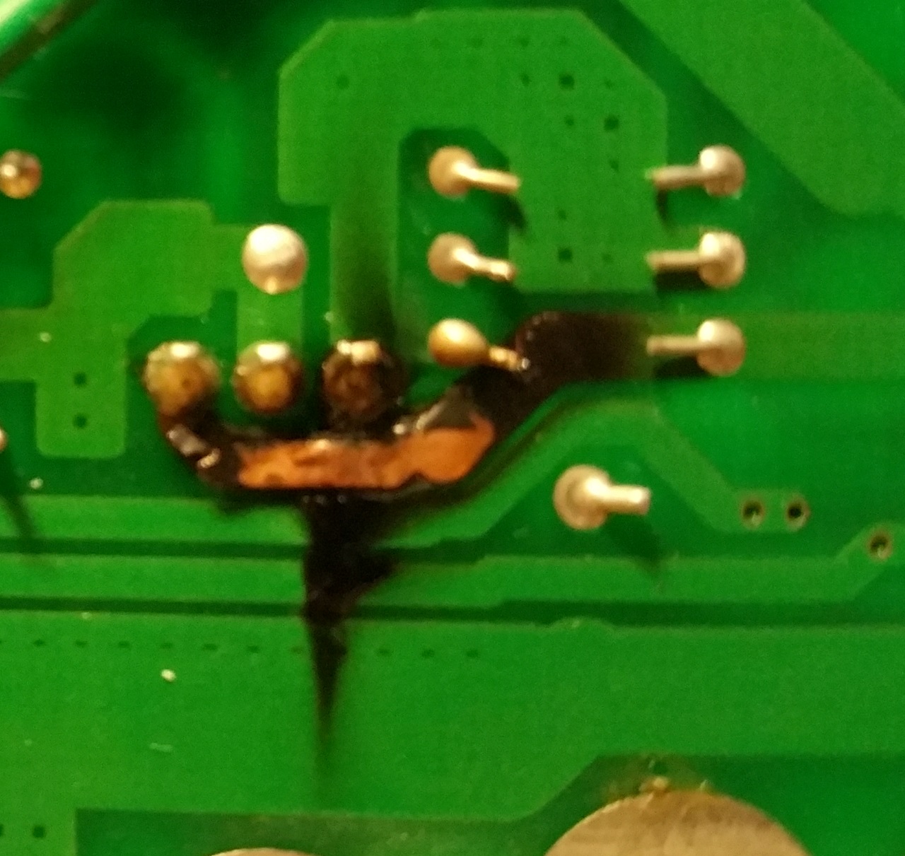
I reconnected all the cables and installed a new battery since the startup showed âBattery low (0.0 volts)â, and decided to install the RAM. And this is where things got weird. None of the diagnostics would recognize the new RAM I just bought. So I took the RAM from the other system and installed it, and I got a strange message on the diagnostics, but after a power cycle it too stopped recognizing the RAM. I installed the ânewâ RAM into unit #1, and it recognized everything just fine. At first, I was convinced this was a problem with the CPU board, so I turned to my buddy Alex Goetsman for a replacement, and he came through with one. During the time I was waiting for Alex, I eventually traced this problem to the power supply (no surprise) and fixed the issue, which was a failing capacitor supplying the +5Vdig rail to the CPU board. Now I have an extra CPU board â âjust in caseâ.
I contacted the person from whom I purchased this unit, asking if he had any experiences with it that might shed some light on why the sample memory wouldnât be recognized. It didnât have the blank that goes in the PRAM slot and I figured I must not be the first person with the access panel off. He was such a great guy to communicate with â I wish I could have given him a six-star rating; he had no idea about what the story was, and even though I explicitly said I didnât want a refund and was confident I could repair the unit, he did something I rarely encounter â he refunded me $100. I profusely thanked him, and it greatly offset the cost of the replacement board I purchased from Alex.
I installed my SMP-2K sampler board here, and Iâll be brief: it works. I works just fine. Happy dance. I did tape the panel blanks to the top of the drive bay with gafferâs tape, just in case I ever decide to sell it and someone wants to part it out, the panel blanks will be back in place.
As I was contemplating the cable replacement as I did previously, I thought it might be a good idea to strand and PET sleeve these cables, so I ordered a roll of ÂŒâ, Âœâ, and Ÿâ PET sleeving. As it turns out, all I needed was the ÂŒâ and Âœâ sleeves â these things open up maybe 3-4 times their diameter. So the SCSI, sampler and floppy drive used the Âœâ sleeves, while the DAC and scanner used the ÂŒâ sleeve. And after a dry run, I managed to come up with a pretty good system for making these.
First, cut the cable to length and terminate it on one end. Measure out the PET sleeving against the cable, leaving an inch at each end. When you cut the PET sleeve, use a lighter to seal both ends because this stuff starts fraying quickly, and lightly melting the ends prevents that. I used a good pair of electronics-grade scissors to cut the sleeve, and then stuck the end down each sleeve opening, and opened the scissors to slightly flare them out. Next, I applied a piece of gafferâs tape on one side of the bare end of the ribbon cable, trimming to be exactly the width of the ribbon, which keeps the stranding process from completely separating the cable. With an X-acto knife, I made incisions between every two or three conductors, and separated these to the hilt of the connector down to the tape. Once the ribbon was stranded, I rolled the bare end as tight as I could with the tape inside, then used a small piece of heat-shrink tubing as a cap, shrinking that down to hold it in place. Expanding the PET sleeve and sliding it over the cable is an easy operation with that heat-shrink cap, and once the sleeve was in place, I then cut two 1.5â pieces of heat shrink tubing for the finished ends and slid them down the sleeve. I pulled the sleeve down enough to allow easy working with the termination. Next, I pulled the âcapâ off the rolled-up end and removed the gafferâs tape, smoothing it out to be a straight enough end for applying the connector. Then, I finished the stranding to the connector housing, stretched the PET sleeve to be about an inch from the connectors, moved the heat-shrink pieces into place and heated those to finish the cable.
Rise and repeat.
I also decided the audio connector cables were too short. Which they were; as with the original ribbon cables, the round black cables still had no slack to reroute, and it bothered me just a bit that the two pairs of cables from the headphone/volume and sampler really didnât need to be two cables; with a shielded 8-conductor cable, combining these cables should be doable. The Molex SPOX connectors are tiny, but inexpensive and readily available at Mouser, so I ordered a quantity of 2 through 6 pin SPOX connectors. When they arrived, I discovered they did not include the pins (who does that?!?), so I ordered 100 since that was the minimum quantity â and theyâre only a nickel apiece, so ~$5 for the pinsâŠ
This did not go well at first; these pins are tiny. After a few hours of trying to crimp these micro-pins with an appropriately small pair of needle-nose pliers, I got right well frustrated and ordered a crimper that had a small 28-30 AWG size. And I proceeded to destroy about $2 worth of pins before I discovered the crimper has a flared end I was reversing, causing the pin crimps to shear off the wires when actually crimpingâŠ
I purchased several feet of 8-conductor Mogami 2789 26AWG wire from Redco audio. I decided the two digital I/O board wires to the sampler, and the volume/headphone wires would each be combined into a single cable, and Iâd replace the scanner power cable, but use Mogami W2948 MIDI cable for this application which was 25AWG, better for power cables; that and I already had I discovered the headphone/volume board didnât use the SPOX connectors, but rather had soldered headers into the board, so I unsoldered those and soldered the wires directly into the holes. And after making up all the cables and installing them, testing the unit for operation, I was able to route and zip-tie all the cables, tuck alongside the edges and down the side of the drive bay.
When replacing the stock case fan with the Noctua, I noticed during the course of all this that the power supply was really hot, and decided to try and help that along by installing a little 40x10mm Noctua fan.
The 40mm fan did require me to drill into the case for two mounting holes that were offset by the diameter of the original holes. Gaffer's tape applied to both sides keeps the metal shavings from any kind of infiltration, and deburring and cleanup with the remainder of tape after removing it gets those pesky metal shavings. Mounting with M3 screws, washers and nuts looks nice:
Loading Image...
 http://theluthers.net/images/K2600R-40fanmount.jpg
http://theluthers.net/images/K2600R-40fanmount.jpg
http://theluthers.net/images/K2600R-40fanmount.jpg http://theluthers.net/images/K2600R-40fanmount.jpg
View on theluthers.net http://theluthers.net/images/K2600R-40fanmount.jpg
Preview by Yahoo
Loading Image...
 http://theluthers.net/images/K2600R-40faninside.jpg
http://theluthers.net/images/K2600R-40faninside.jpg
http://theluthers.net/images/K2600R-40faninside.jpg http://theluthers.net/images/K2600R-40faninside.jpg
View on theluthers.net http://theluthers.net/images/K2600R-40faninside.jpg
Preview by Yahoo
Some quick calculation showed Iâd be pulling 0.15A combining both fans, which should be below the requirements of the original Panaflo case fan. So I created a two-outlet header attached to a 2-pin SPOX connector:
Loading Image...
 http://theluthers.net/images/Noctua-header.jpg
http://theluthers.net/images/Noctua-header.jpg
http://theluthers.net/images/Noctua-header.jpg http://theluthers.net/images/Noctua-header.jpg
View on theluthers.net http://theluthers.net/images/Noctua-header.jpg
Preview by Yahoo
This setup allowed me to preserve the standard headers on the fans, and when I tested them prior to installation I promptly blew the fuse. I blew another fuse when trying to read the amp draw. I figured since I was powering the SCSI2SD card with the termination power, I could just install the header in the HDD power connector, so I popped the pins out and installed them in a 4-pin SPOX connector, connected the header and â you guessed it â blew yet another fuse. After all the work I put into mounting this fan I wasnât going to let it go to waste, so I clipped the fan ends and installed a 2-pin SPOX connector on the 40mm fan and the 4-pin connector on the case fan into the HDD power. No more blown fuses.
After this system was mostly reassembled, as Iâm running the diagnostics and looking things over I noticed the two 7805 VRMs on the audio board were hot, way too hot. I looked at this as an opportunity for improvement. I first looked at the small TO-220 heat sinks I had around, but even after clipping the support lead it was just too tall for this application, and I had my doubts about the spacing. Then I remembered the set of Thermaltake chipset heatsinks that came with the RAM heat spreaders I bought some years ago, just sitting in a drawer. I pulled one out and at 58mm, they were way too wide for this application, but the 20mm height was just about perfect. I cut it in half:
Loading Image...
 http://theluthers.net/images/heatsinks.jpg
http://theluthers.net/images/heatsinks.jpg
http://theluthers.net/images/heatsinks.jpg http://theluthers.net/images/heatsinks.jpg
View on theluthers.net http://theluthers.net/images/heatsinks.jpg
Preview by Yahoo
⊠spent several minutes with a product called âGoof-offâ and some paper towels to remove the adhesive. There are two of these per kit, and only one had the adhesive; a fact I wish I had been aware of earlier. I squared the heatsink against the VRMs and marked off the centers of the mounting holes. I then used a nifty little combination drill and tap set, the smallest bit of which was an M3x0.5. An application of penetrating oil and the âthree steps forward, one step backâ tapping process and I had a pair of nice M3 mounting holes in the heat sink.
Loading Image...
 http://theluthers.net/images/hs-tapped.jpg
http://theluthers.net/images/hs-tapped.jpg
http://theluthers.net/images/hs-tapped.jpg http://theluthers.net/images/hs-tapped.jpg
View on theluthers.net http://theluthers.net/images/hs-tapped.jpg
Preview by Yahoo
I could have probably left the heatsink as is at this point, perhaps even slightly countersinking the opening for deburring purposes, but if youâre familiar with the application of heatsinks, you know one needs to have as smooth a mating surface as possible for maximum heat transfer. So I used some 440-grit sandpaper (hey, itâs what I had on hand) and smoothed the cut end and hone the surface. I finished this up using a sheet of cheap office paper to produce a surface much better than the original.
Loading Image...
 http://theluthers.net/images/hs-honed.jpg
http://theluthers.net/images/hs-honed.jpg
http://theluthers.net/images/hs-honed.jpg http://theluthers.net/images/hs-honed.jpg
View on theluthers.net http://theluthers.net/images/hs-honed.jpg
Preview by Yahoo
Applying some Noctua NT-H1 thermal paste to the heat sink, using that to hold a mica insulator in place and a dab of the paste on it provides good heat transfer while the mica insures insulation between it and the transistorâs ground. A nylon bushing and M3 screw completed this little operation.
Loading Image...
 http://theluthers.net/images/hs-installed.jpg
http://theluthers.net/images/hs-installed.jpg
http://theluthers.net/images/hs-installed.jpg http://theluthers.net/images/hs-installed.jpg
View on theluthers.net http://theluthers.net/images/hs-installed.jpg
Preview by Yahoo
And the K2600R is complete:
Loading Image...
 http://theluthers.net/images/K2600R-complete.jpg
http://theluthers.net/images/K2600R-complete.jpg
http://theluthers.net/images/K2600R-complete.jpg http://theluthers.net/images/K2600R-complete.jpg
View on theluthers.net http://theluthers.net/images/K2600R-complete.jpg
Preview by Yahoo
As Iâm buttoning this up, I got the idea Iâd like to try my hand at sleeving the power supply cables in paracord. This came from my research into wrapping the ribbon cables in PET sleeving, and Iâll be completely honest here and say it serves no purpose other than vanity. So I pulled the main power supply cable from the CPU board since it was the only one not twisted and began the process. Using a small common screwdriver, I carefully pried up the plastic tab which allowed the pin to unlock and slide out. I knew I had to coat the pin in something to keep it from snagging the cord, so I used some heat-shrink tubing to cover the pin and allow it to slide down the cord. I cut the paracord to length and removed the nylon cores, then slid the pin into one end. inchworming my way down. Once I had the jacket about halfway on, I slid smaller pieces of heatshrink over it to seal the finished ends after removing the heatshrink cap.
Loading Image...
 http://theluthers.net/images/pscables-proc.jpg
http://theluthers.net/images/pscables-proc.jpg
http://theluthers.net/images/pscables-proc.jpg http://theluthers.net/images/pscables-proc.jpg
View on theluthers.net http://theluthers.net/images/pscables-proc.jpg
Preview by Yahoo
I got lucky with my first two cables. On my third attempt, one end started fraying as I was almost complete. So for the remainder, I used a lighter to melt the ends and the expansion of scissors to expand the opening, a lesson I must not have taken to heart with all the PET sleeving I did earlier.
Loading Image...
 http://theluthers.net/images/pscables-wrapped.jpg
http://theluthers.net/images/pscables-wrapped.jpg
http://theluthers.net/images/pscables-wrapped.jpg http://theluthers.net/images/pscables-wrapped.jpg
View on theluthers.net http://theluthers.net/images/pscables-wrapped.jpg
Preview by Yahoo
All I had to do was keep them in place, so I used some nylon thread to stitch the cables together at several points along the length, and this little project comes to a close.
Loading Image...
 http://theluthers.net/images/K2600R-pscables-installed.jpg
http://theluthers.net/images/K2600R-pscables-installed.jpg
http://theluthers.net/images/K2600R-pscables-installed.j... http://theluthers.net/images/K2600R-pscables-installed.jpg
View on theluthers.net http://theluthers.net/images/K2600R-pscables-installed.jpg
Preview by Yahoo
Yeah, I know; this serves no really useful purpose, but I gotta say â it sure looks cool! Now all to do is go through the diagnostics one last time to verify installation and access to the RAM:
Loading Image...
 http://theluthers.net/images/K2600R-ram.jpg
http://theluthers.net/images/K2600R-ram.jpg
http://theluthers.net/images/K2600R-ram.jpg http://theluthers.net/images/K2600R-ram.jpg
View on theluthers.net http://theluthers.net/images/K2600R-ram.jpg
Preview by Yahoo
The PRAM:
Loading Image...
 http://theluthers.net/images/K2600R-pram.jpg
http://theluthers.net/images/K2600R-pram.jpg
http://theluthers.net/images/K2600R-pram.jpg http://theluthers.net/images/K2600R-pram.jpg
View on theluthers.net http://theluthers.net/images/K2600R-pram.jpg
Preview by Yahoo
The ROM installation:
Loading Image...
 http://theluthers.net/images/K2600R-rom.jpg
http://theluthers.net/images/K2600R-rom.jpg
http://theluthers.net/images/K2600R-rom.jpg http://theluthers.net/images/K2600R-rom.jpg
View on theluthers.net http://theluthers.net/images/K2600R-rom.jpg
Preview by Yahoo
And finally access to the SCSI2SD devices:
Loading Image...
 http://theluthers.net/images/K2600R-scsi.jpg
http://theluthers.net/images/K2600R-scsi.jpg
http://theluthers.net/images/K2600R-scsi.jpg http://theluthers.net/images/K2600R-scsi.jpg
View on theluthers.net http://theluthers.net/images/K2600R-scsi.jpg
Preview by Yahoo
So, after all this, whatâs next? Really, whatâs left is a better question. I wouldnât mind replacing the displays with a white-on-black LED versions. The PSU could stand to have the 220uf C6 capacitor replaced with a 100uf cap, per Kurzweilâs recommendation, and if Iâm in there Iâd probably replace that variable resistor R9 for the +12V adjustment with a 100K precision multi-turn pot.
Having worked on a K2000, a K2500 and now a K2600 series, I can see the progression. All along the K series, Kurzweil built these things like tanks. Some of the things like the volume/headphone board are just common from the K2000 series (says so right on the silkscreen). But other things like the mounting tray for the audio I/O board â itâs about time.
Big shout out to Alex Gotesman -- dude, you always come through.
Reply to sender . Reply to group . Reply via Web Post . All Messages (3) . Top ^
1b
Re: My adventures with K2600 rack units
Tue Nov 14, 2017 10:04 am (PST) . Posted by:
"Jerker Lindborg" fairlightcmi
Great work!
I can also vouch for Noctua fans as I have done that to my K2500S and K2600XS.
Cheers
Skickat från min iPhone
This is going to be a long, meandering post; it will probably qualify as a short novel by the time I finish, so if for you âtl;drâ is a thing, please, just mosey along and donât even try. This was a few months in the making, but I wanted to share my adventures with a pair of K2600Rs I purchasedâŠ
I love me some Kurzweil. I started with a K2000R back in the late 1990âs (which I still have), then eventually moved up to a K2500XS with everything but the KDFX option. I decided I have more keyboards than Iâll ever possibly use and that rack mount modules are the way to go, and purchased a K2500RS. I then spent the next several months diagnosing a problem that turned out to be a bad engine board, and the next few years patiently waiting for a good price on a KDFX board.
Iâve watched the K2600R prices hover around the $1,200 mark (when they became available), placing them out of my price range; so when a K2600RS came on sale for around $600, I pounced. A couple months later I came across one without the sampling option for significantly less money, and I pounced again. And this is where the fun startsâŠ
K2600RS (#1) was in great shape. All I had to do was come up with the expansion ROMs, PRAM and memory to populate both systems. I had a set of 128MB of RAM from my previous adventure with my 2500 rack unit that needed the engine board swapped out, which was an earlier revision requiring my 2 64MB DIMMS to be replaced with 4 32MB modules. I also decided Iâd try installing SCSI2SD boards in these systems, so I acquired a couple. During this long Kurzweil ownership/repair/upgrade process I managed to acquire many K2500 parts, including a spare sampling option. I heard the SMP-2X (for the K2600 series) was actually a re-screened SMP-2R (from the K2500 series) and I wanted to install my sampling option and see if it really worked.
K2600 #1 needed the SCSI2SD, RAM, PRAM and ROM options installed.
K2600 #2 needed the above plus the sampling option. Also, I wanted to replace the fans in both units with a lower current, silent Noctua fan like I did for my 2500 rack.
So I opened up the top case of #1 and hereâs where the fun begins. First, it was dirty inside. Second, it seemed like Kurzweil designed the thing to look like a ribbon cable factory exploded inside it!
http://theluthers.net/images/K2600R-pback.jpg
http://theluthers.net/images/K2600R-pback.jpg
View on theluthers.net
Preview by Yahoo
Sorry for not taking initial pictures; I found these on the internet and itâs what mine looked like when I opened them.
http://theluthers.net/images/K2500-after.jpg
http://theluthers.net/images/K2500-after.jpg
View on theluthers.net
Preview by Yahoo
⊠but the K2600s were a challenge because, as well engineered as these units are (and more on that later), the cable management in these was as tight as it was sloppy, meaning absolutely no slack to fold or bend or route. I suppose I should probably say a little something about myself and history at this point, specifically that I have a more-than-nodding acquaintance with electronic troubleshooting and repair, and that Iâve been building computer systems from components since 1986(-ish). Also, Iâm not a âneat freakâ per-se, but I do have a weird compulsion about keeping my gear tidy and cool where it counts, and upon cracking open the case of these guys, my first thought was âhow does air move around in here?â
http://theluthers.net/images/cable-making.jpg
http://theluthers.net/images/cable-making.jpg
View on theluthers.net
Preview by Yahoo
Hereâs a tip for anyone making ribbon cables: a paper cutter with a swing arm is a great tool for making perfectly square cuts in ribbon cable. Thatâs all Iâm sayinâ⊠After all the measuring, cutting, crimping, bending, and folding, I realized the SCSI cable from the underside of the CPU board wasnât ever going to look quite right, so I decided to rip it down the middle and fold it over itself at both connector ends, which made it a nice run from the underside of the board, over and in front of the drive tray.
http://theluthers.net/images/K2600RS-scsi-installed.jpg
http://theluthers.net/images/K2600RS-scsi-installed.jpg
View on theluthers.net
Preview by Yahoo
http://theluthers.net/images/flat-cable-harness.jpg
http://theluthers.net/images/flat-cable-harness.jpg
View on theluthers.net
Preview by Yahoo
Upon installation, cable management was fairly complete; the only thing I did not do at this point was replace the scanner board cable since I hadnât purchased any 14-pin connectors, which I did now. The sampler cable was about .5cm too short and the installed cable harness isn't exactly straight, but I was going to just be happy with this attempt.
http://theluthers.net/images/K2600R-flat-installed.jpg
http://theluthers.net/images/K2600R-flat-installed.jpg
View on theluthers.net
Preview by Yahoo
At this point in time, I purchased a couple metal 3.5 inch SSD mounting trays, mostly because I couldnât find any plastic ones I could use to mount the SCSI2SD cards. Well, thatâs not entirely true; the metal trays were ~$1 each shipped, and the plastic trays I found were going to be around $12 plus shipping, and I deferred to the âless expensiveâ metal trays. These turned out to be a bit of a challenge I overcame by using four 8mm nylon spacers which I epoxied to the tray. Since the SCSI2SD card only has two mounting holes in the back, I figured Iâd have to fill the spacer with epoxy and drill it out for screw holes, but as I was fitting these I found the holes werenât perfectly aligned with my spacers, and the resulting gap would be just wide enough for an M3 screw to burr into the spacer against the cardâs inside mounting hole edge. Problem solved! I discovered the SCSI2SD would draw the necessary power from the on-board SCSI terminator, which saved me from having to manufacture a custom power cable.
Now I got the bright idea that I could replace the floppy drive with a slim version, and use the extra head space on the face plate to mount an LED, SD and micro USB extension cable from the SCSI2SD card; all Iâd need to do was make up a quick jig to clamp across the longest point and adjust a couple blocks to the necessary widths and use my Dremmelâs router attachment with the miniature burring head to cut plastic. And so the side trip begins. I was able to Ebay a couple Teac FD05HG drives for $15 using a âMake Offerâ, and when they came I discovered the floppy connector was a flat FFC 25-pin connector. So I found a couple connector boards with this connector and 34-pin IDC floppy connectors â in China. So I ordered two of them. Iâll just skip to the bottom of the page here and tell you they didnât work. [sigh] More parts for the binâŠ
I replaced the stock Panasonic fan with a Noctua NF-A9 PWM. It uses slightly less power than the stock Panasonic Panaflo FBA09A12M (1.2W/0.1A, vs. 2.4W/0.2A - 12V), and the Noctua moves only slightly less air (46.4 cfm vs. 48cfm), but with the internal space opened up allowing air to circulate better through the units, Iâm satisfied the cooling requirements are more than being met. For this installation I simply clipped off the fan lead from the old fan, and repurposed one of the LNA cables in the Noctua kit for its jacketing (nice stuff, that). I carefully slipped a couple pieces of heat-shrink over this to cover the splice ends over the jacketing. Then I clipped off the Noctuaâs terminal, slid down the jacketing enough to slip a couple pieces of tiny heat-shrink tubing and strip the leads, soldered each of the 12V and ground wires together, sealing the PWM leads and individually heat-shrinking all of these wires, then heat-shrinking the connector end and the splice area. I also installed a fan grille over the exposed blades, just for that âextra touch.â The Noctua fans are nearly silent; you really have to put your ear next to one to hear if itâs really on. Many people complain about the noisy Kurzweil fans â I highly recommend this fan over the stock if noise is an issue.
Finally, I installed the ROM, RAM and PRAM, replaced the battery, checked for operation (actually a continuous process, but still), formatted all the SD partitions, updated the OS to 4.11, installed objects for the Orchestral, Contemporary, Dynamic Piano and Vintage Electric ROMS, and enjoyed my well and truly updated K2600RS.
http://theluthers.net/images/K2600R1-finished.jpg
http://theluthers.net/images/K2600R1-finished.jpg
View on theluthers.net
Preview by Yahoo
Moving on to unit #2âŠ
This was a K2600R, no sampling option. But I had a spare SMP/2K from a box of K2500X parts I picked up at a pretty steep discount (essentially the guts of a K2500X, which I got for spares, you know, âjust in caseâ). I actually purchased this for the sampling option and paid less for the whole box that I would the sampling option, so, bonusâŠ
I should be clear about this point: I really wasnât looking to purchase another K2600 rack. But I still had âKurzweil K2600Râ in my Ebay saved searches, and when it showed up the âBuy it Nowâ price was just too insanely low to pass up. Free shipping to boot, and all the pictures showed a working unit, so I committed.
If I thought unit #1 was dirty inside, unit #2 was just filthy. Giant dust balls everywhere. I even pulled the faceplate from this unit and big dust balls fell out. So, the very first thing I did was remove all the ribbon cables, take it outside and perform a generous cleaning with my air compressor.
I reconnected all the cables and installed a new battery since the startup showed âBattery low (0.0 volts)â, and decided to install the RAM. And this is where things got weird. None of the diagnostics would recognize the new RAM I just bought. So I took the RAM from the other system and installed it, and I got a strange message on the diagnostics, but after a power cycle it too stopped recognizing the RAM. I installed the ânewâ RAM into unit #1, and it recognized everything just fine. At first, I was convinced this was a problem with the CPU board, so I turned to my buddy Alex Goetsman for a replacement, and he came through with one. During the time I was waiting for Alex, I eventually traced this problem to the power supply (no surprise) and fixed the issue, which was a failing capacitor supplying the +5Vdig rail to the CPU board. Now I have an extra CPU board â âjust in caseâ.
I contacted the person from whom I purchased this unit, asking if he had any experiences with it that might shed some light on why the sample memory wouldnât be recognized. It didnât have the blank that goes in the PRAM slot and I figured I must not be the first person with the access panel off. He was such a great guy to communicate with â I wish I could have given him a six-star rating; he had no idea about what the story was, and even though I explicitly said I didnât want a refund and was confident I could repair the unit, he did something I rarely encounter â he refunded me $100. I profusely thanked him, and it greatly offset the cost of the replacement board I purchased from Alex.
I installed my SMP-2K sampler board here, and Iâll be brief: it works. I works just fine. Happy dance. I did tape the panel blanks to the top of the drive bay with gafferâs tape, just in case I ever decide to sell it and someone wants to part it out, the panel blanks will be back in place.
As I was contemplating the cable replacement as I did previously, I thought it might be a good idea to strand and PET sleeve these cables, so I ordered a roll of ÂŒâ, Âœâ, and Ÿâ PET sleeving. As it turns out, all I needed was the ÂŒâ and Âœâ sleeves â these things open up maybe 3-4 times their diameter. So the SCSI, sampler and floppy drive used the Âœâ sleeves, while the DAC and scanner used the ÂŒâ sleeve. And after a dry run, I managed to come up with a pretty good system for making these.
First, cut the cable to length and terminate it on one end. Measure out the PET sleeving against the cable, leaving an inch at each end. When you cut the PET sleeve, use a lighter to seal both ends because this stuff starts fraying quickly, and lightly melting the ends prevents that. I used a good pair of electronics-grade scissors to cut the sleeve, and then stuck the end down each sleeve opening, and opened the scissors to slightly flare them out. Next, I applied a piece of gafferâs tape on one side of the bare end of the ribbon cable, trimming to be exactly the width of the ribbon, which keeps the stranding process from completely separating the cable. With an X-acto knife, I made incisions between every two or three conductors, and separated these to the hilt of the connector down to the tape. Once the ribbon was stranded, I rolled the bare end as tight as I could with the tape inside, then used a small piece of heat-shrink tubing as a cap, shrinking that down to hold it in place. Expanding the PET sleeve and sliding it over the cable is an easy operation with that heat-shrink cap, and once the sleeve was in place, I then cut two 1.5â pieces of heat shrink tubing for the finished ends and slid them down the sleeve. I pulled the sleeve down enough to allow easy working with the termination. Next, I pulled the âcapâ off the rolled-up end and removed the gafferâs tape, smoothing it out to be a straight enough end for applying the connector. Then, I finished the stranding to the connector housing, stretched the PET sleeve to be about an inch from the connectors, moved the heat-shrink pieces into place and heated those to finish the cable.
Rise and repeat.
I also decided the audio connector cables were too short. Which they were; as with the original ribbon cables, the round black cables still had no slack to reroute, and it bothered me just a bit that the two pairs of cables from the headphone/volume and sampler really didnât need to be two cables; with a shielded 8-conductor cable, combining these cables should be doable. The Molex SPOX connectors are tiny, but inexpensive and readily available at Mouser, so I ordered a quantity of 2 through 6 pin SPOX connectors. When they arrived, I discovered they did not include the pins (who does that?!?), so I ordered 100 since that was the minimum quantity â and theyâre only a nickel apiece, so ~$5 for the pinsâŠ
This did not go well at first; these pins are tiny. After a few hours of trying to crimp these micro-pins with an appropriately small pair of needle-nose pliers, I got right well frustrated and ordered a crimper that had a small 28-30 AWG size. And I proceeded to destroy about $2 worth of pins before I discovered the crimper has a flared end I was reversing, causing the pin crimps to shear off the wires when actually crimpingâŠ
I purchased several feet of 8-conductor Mogami 2789 26AWG wire from Redco audio. I decided the two digital I/O board wires to the sampler, and the volume/headphone wires would each be combined into a single cable, and Iâd replace the scanner power cable, but use Mogami W2948 MIDI cable for this application which was 25AWG, better for power cables; that and I already had I discovered the headphone/volume board didnât use the SPOX connectors, but rather had soldered headers into the board, so I unsoldered those and soldered the wires directly into the holes. And after making up all the cables and installing them, testing the unit for operation, I was able to route and zip-tie all the cables, tuck alongside the edges and down the side of the drive bay.
When replacing the stock case fan with the Noctua, I noticed during the course of all this that the power supply was really hot, and decided to try and help that along by installing a little 40x10mm Noctua fan.
http://theluthers.net/images/K2600R-40fanmount.jpg
http://theluthers.net/images/K2600R-40fanmount.jpg
View on theluthers.net
Preview by Yahoo
http://theluthers.net/images/K2600R-40faninside.jpg
http://theluthers.net/images/K2600R-40faninside.jpg
View on theluthers.net
Preview by Yahoo
http://theluthers.net/images/Noctua-header.jpg
http://theluthers.net/images/Noctua-header.jpg
View on theluthers.net
Preview by Yahoo
This setup allowed me to preserve the standard headers on the fans, and when I tested them prior to installation I promptly blew the fuse. I blew another fuse when trying to read the amp draw. I figured since I was powering the SCSI2SD card with the termination power, I could just install the header in the HDD power connector, so I popped the pins out and installed them in a 4-pin SPOX connector, connected the header and â you guessed it â blew yet another fuse. After all the work I put into mounting this fan I wasnât going to let it go to waste, so I clipped the fan ends and installed a 2-pin SPOX connector on the 40mm fan and the 4-pin connector on the case fan into the HDD power. No more blown fuses.
http://theluthers.net/images/heatsinks.jpg
http://theluthers.net/images/heatsinks.jpg
View on theluthers.net
Preview by Yahoo
⊠spent several minutes with a product called âGoof-offâ and some paper towels to remove the adhesive. There are two of these per kit, and only one had the adhesive; a fact I wish I had been aware of earlier. I squared the heatsink against the VRMs and marked off the centers of the mounting holes. I then used a nifty little combination drill and tap set, the smallest bit of which was an M3x0.5. An application of penetrating oil and the âthree steps forward, one step backâ tapping process and I had a pair of nice M3 mounting holes in the heat sink.
http://theluthers.net/images/hs-tapped.jpg
http://theluthers.net/images/hs-tapped.jpg
View on theluthers.net
Preview by Yahoo
I could have probably left the heatsink as is at this point, perhaps even slightly countersinking the opening for deburring purposes, but if youâre familiar with the application of heatsinks, you know one needs to have as smooth a mating surface as possible for maximum heat transfer. So I used some 440-grit sandpaper (hey, itâs what I had on hand) and smoothed the cut end and hone the surface. I finished this up using a sheet of cheap office paper to produce a surface much better than the original.
http://theluthers.net/images/hs-honed.jpg
http://theluthers.net/images/hs-honed.jpg
View on theluthers.net
Preview by Yahoo
Applying some Noctua NT-H1 thermal paste to the heat sink, using that to hold a mica insulator in place and a dab of the paste on it provides good heat transfer while the mica insures insulation between it and the transistorâs ground. A nylon bushing and M3 screw completed this little operation.
http://theluthers.net/images/hs-installed.jpg
http://theluthers.net/images/hs-installed.jpg
View on theluthers.net
Preview by Yahoo
http://theluthers.net/images/K2600R-complete.jpg
http://theluthers.net/images/K2600R-complete.jpg
View on theluthers.net
Preview by Yahoo
As Iâm buttoning this up, I got the idea Iâd like to try my hand at sleeving the power supply cables in paracord. This came from my research into wrapping the ribbon cables in PET sleeving, and Iâll be completely honest here and say it serves no purpose other than vanity. So I pulled the main power supply cable from the CPU board since it was the only one not twisted and began the process. Using a small common screwdriver, I carefully pried up the plastic tab which allowed the pin to unlock and slide out. I knew I had to coat the pin in something to keep it from snagging the cord, so I used some heat-shrink tubing to cover the pin and allow it to slide down the cord. I cut the paracord to length and removed the nylon cores, then slid the pin into one end. inchworming my way down. Once I had the jacket about halfway on, I slid smaller pieces of heatshrink over it to seal the finished ends after removing the heatshrink cap.
http://theluthers.net/images/pscables-proc.jpg
http://theluthers.net/images/pscables-proc.jpg
View on theluthers.net
Preview by Yahoo
I got lucky with my first two cables. On my third attempt, one end started fraying as I was almost complete. So for the remainder, I used a lighter to melt the ends and the expansion of scissors to expand the opening, a lesson I must not have taken to heart with all the PET sleeving I did earlier.
http://theluthers.net/images/pscables-wrapped.jpg
http://theluthers.net/images/pscables-wrapped.jpg
View on theluthers.net
Preview by Yahoo
All I had to do was keep them in place, so I used some nylon thread to stitch the cables together at several points along the length, and this little project comes to a close.
http://theluthers.net/images/K2600R-pscables-installed.jpg
http://theluthers.net/images/K2600R-pscables-installed.j...
View on theluthers.net
Preview by Yahoo
http://theluthers.net/images/K2600R-ram.jpg
http://theluthers.net/images/K2600R-ram.jpg
View on theluthers.net
Preview by Yahoo
http://theluthers.net/images/K2600R-pram.jpg
http://theluthers.net/images/K2600R-pram.jpg
View on theluthers.net
Preview by Yahoo
http://theluthers.net/images/K2600R-rom.jpg
http://theluthers.net/images/K2600R-rom.jpg
View on theluthers.net
Preview by Yahoo
http://theluthers.net/images/K2600R-scsi.jpg
http://theluthers.net/images/K2600R-scsi.jpg
View on theluthers.net
Preview by Yahoo
So, after all this, whatâs next? Really, whatâs left is a better question. I wouldnât mind replacing the displays with a white-on-black LED versions. The PSU could stand to have the 220uf C6 capacitor replaced with a 100uf cap, per Kurzweilâs recommendation, and if Iâm in there Iâd probably replace that variable resistor R9 for the +12V adjustment with a 100K precision multi-turn pot.
Having worked on a K2000, a K2500 and now a K2600 series, I can see the progression. All along the K series, Kurzweil built these things like tanks. Some of the things like the volume/headphone board are just common from the K2000 series (says so right on the silkscreen). But other things like the mounting tray for the audio I/O board â itâs about time.
Big shout out to Alex Gotesman -- dude, you always come through.
Reply to sender . Reply to group . Reply via Web Post . All Messages (3) . Top ^I love me some Kurzweil. I started with a K2000R back in the late 1990âs (which I still have), then eventually moved up to a K2500XS with everything but the KDFX option. I decided I have more keyboards than Iâll ever possibly use and that rack mount modules are the way to go, and purchased a K2500RS. I then spent the next several months diagnosing a problem that turned out to be a bad engine board, and the next few years patiently waiting for a good price on a KDFX board.
Iâve watched the K2600R prices hover around the $1,200 mark (when they became available), placing them out of my price range; so when a K2600RS came on sale for around $600, I pounced. A couple months later I came across one without the sampling option for significantly less money, and I pounced again. And this is where the fun startsâŠ
K2600RS (#1) was in great shape. All I had to do was come up with the expansion ROMs, PRAM and memory to populate both systems. I had a set of 128MB of RAM from my previous adventure with my 2500 rack unit that needed the engine board swapped out, which was an earlier revision requiring my 2 64MB DIMMS to be replaced with 4 32MB modules. I also decided Iâd try installing SCSI2SD boards in these systems, so I acquired a couple. During this long Kurzweil ownership/repair/upgrade process I managed to acquire many K2500 parts, including a spare sampling option. I heard the SMP-2X (for the K2600 series) was actually a re-screened SMP-2R (from the K2500 series) and I wanted to install my sampling option and see if it really worked.
K2600 #1 needed the SCSI2SD, RAM, PRAM and ROM options installed.
K2600 #2 needed the above plus the sampling option. Also, I wanted to replace the fans in both units with a lower current, silent Noctua fan like I did for my 2500 rack.
So I opened up the top case of #1 and hereâs where the fun begins. First, it was dirty inside. Second, it seemed like Kurzweil designed the thing to look like a ribbon cable factory exploded inside it!
http://theluthers.net/images/K2600R-pback.jpg
http://theluthers.net/images/K2600R-pback.jpg
View on theluthers.net
Preview by Yahoo
Sorry for not taking initial pictures; I found these on the internet and itâs what mine looked like when I opened them.
http://theluthers.net/images/K2500-after.jpg
http://theluthers.net/images/K2500-after.jpg
View on theluthers.net
Preview by Yahoo
⊠but the K2600s were a challenge because, as well engineered as these units are (and more on that later), the cable management in these was as tight as it was sloppy, meaning absolutely no slack to fold or bend or route. I suppose I should probably say a little something about myself and history at this point, specifically that I have a more-than-nodding acquaintance with electronic troubleshooting and repair, and that Iâve been building computer systems from components since 1986(-ish). Also, Iâm not a âneat freakâ per-se, but I do have a weird compulsion about keeping my gear tidy and cool where it counts, and upon cracking open the case of these guys, my first thought was âhow does air move around in here?â
http://theluthers.net/images/cable-making.jpg
http://theluthers.net/images/cable-making.jpg
View on theluthers.net
Preview by Yahoo
Hereâs a tip for anyone making ribbon cables: a paper cutter with a swing arm is a great tool for making perfectly square cuts in ribbon cable. Thatâs all Iâm sayinâ⊠After all the measuring, cutting, crimping, bending, and folding, I realized the SCSI cable from the underside of the CPU board wasnât ever going to look quite right, so I decided to rip it down the middle and fold it over itself at both connector ends, which made it a nice run from the underside of the board, over and in front of the drive tray.
http://theluthers.net/images/K2600RS-scsi-installed.jpg
http://theluthers.net/images/K2600RS-scsi-installed.jpg
View on theluthers.net
Preview by Yahoo
http://theluthers.net/images/flat-cable-harness.jpg
http://theluthers.net/images/flat-cable-harness.jpg
View on theluthers.net
Preview by Yahoo
Upon installation, cable management was fairly complete; the only thing I did not do at this point was replace the scanner board cable since I hadnât purchased any 14-pin connectors, which I did now. The sampler cable was about .5cm too short and the installed cable harness isn't exactly straight, but I was going to just be happy with this attempt.
http://theluthers.net/images/K2600R-flat-installed.jpg
http://theluthers.net/images/K2600R-flat-installed.jpg
View on theluthers.net
Preview by Yahoo
At this point in time, I purchased a couple metal 3.5 inch SSD mounting trays, mostly because I couldnât find any plastic ones I could use to mount the SCSI2SD cards. Well, thatâs not entirely true; the metal trays were ~$1 each shipped, and the plastic trays I found were going to be around $12 plus shipping, and I deferred to the âless expensiveâ metal trays. These turned out to be a bit of a challenge I overcame by using four 8mm nylon spacers which I epoxied to the tray. Since the SCSI2SD card only has two mounting holes in the back, I figured Iâd have to fill the spacer with epoxy and drill it out for screw holes, but as I was fitting these I found the holes werenât perfectly aligned with my spacers, and the resulting gap would be just wide enough for an M3 screw to burr into the spacer against the cardâs inside mounting hole edge. Problem solved! I discovered the SCSI2SD would draw the necessary power from the on-board SCSI terminator, which saved me from having to manufacture a custom power cable.
Now I got the bright idea that I could replace the floppy drive with a slim version, and use the extra head space on the face plate to mount an LED, SD and micro USB extension cable from the SCSI2SD card; all Iâd need to do was make up a quick jig to clamp across the longest point and adjust a couple blocks to the necessary widths and use my Dremmelâs router attachment with the miniature burring head to cut plastic. And so the side trip begins. I was able to Ebay a couple Teac FD05HG drives for $15 using a âMake Offerâ, and when they came I discovered the floppy connector was a flat FFC 25-pin connector. So I found a couple connector boards with this connector and 34-pin IDC floppy connectors â in China. So I ordered two of them. Iâll just skip to the bottom of the page here and tell you they didnât work. [sigh] More parts for the binâŠ
I replaced the stock Panasonic fan with a Noctua NF-A9 PWM. It uses slightly less power than the stock Panasonic Panaflo FBA09A12M (1.2W/0.1A, vs. 2.4W/0.2A - 12V), and the Noctua moves only slightly less air (46.4 cfm vs. 48cfm), but with the internal space opened up allowing air to circulate better through the units, Iâm satisfied the cooling requirements are more than being met. For this installation I simply clipped off the fan lead from the old fan, and repurposed one of the LNA cables in the Noctua kit for its jacketing (nice stuff, that). I carefully slipped a couple pieces of heat-shrink over this to cover the splice ends over the jacketing. Then I clipped off the Noctuaâs terminal, slid down the jacketing enough to slip a couple pieces of tiny heat-shrink tubing and strip the leads, soldered each of the 12V and ground wires together, sealing the PWM leads and individually heat-shrinking all of these wires, then heat-shrinking the connector end and the splice area. I also installed a fan grille over the exposed blades, just for that âextra touch.â The Noctua fans are nearly silent; you really have to put your ear next to one to hear if itâs really on. Many people complain about the noisy Kurzweil fans â I highly recommend this fan over the stock if noise is an issue.
Finally, I installed the ROM, RAM and PRAM, replaced the battery, checked for operation (actually a continuous process, but still), formatted all the SD partitions, updated the OS to 4.11, installed objects for the Orchestral, Contemporary, Dynamic Piano and Vintage Electric ROMS, and enjoyed my well and truly updated K2600RS.
http://theluthers.net/images/K2600R1-finished.jpg
http://theluthers.net/images/K2600R1-finished.jpg
View on theluthers.net
Preview by Yahoo
Moving on to unit #2âŠ
This was a K2600R, no sampling option. But I had a spare SMP/2K from a box of K2500X parts I picked up at a pretty steep discount (essentially the guts of a K2500X, which I got for spares, you know, âjust in caseâ). I actually purchased this for the sampling option and paid less for the whole box that I would the sampling option, so, bonusâŠ
I should be clear about this point: I really wasnât looking to purchase another K2600 rack. But I still had âKurzweil K2600Râ in my Ebay saved searches, and when it showed up the âBuy it Nowâ price was just too insanely low to pass up. Free shipping to boot, and all the pictures showed a working unit, so I committed.
If I thought unit #1 was dirty inside, unit #2 was just filthy. Giant dust balls everywhere. I even pulled the faceplate from this unit and big dust balls fell out. So, the very first thing I did was remove all the ribbon cables, take it outside and perform a generous cleaning with my air compressor.
I reconnected all the cables and installed a new battery since the startup showed âBattery low (0.0 volts)â, and decided to install the RAM. And this is where things got weird. None of the diagnostics would recognize the new RAM I just bought. So I took the RAM from the other system and installed it, and I got a strange message on the diagnostics, but after a power cycle it too stopped recognizing the RAM. I installed the ânewâ RAM into unit #1, and it recognized everything just fine. At first, I was convinced this was a problem with the CPU board, so I turned to my buddy Alex Goetsman for a replacement, and he came through with one. During the time I was waiting for Alex, I eventually traced this problem to the power supply (no surprise) and fixed the issue, which was a failing capacitor supplying the +5Vdig rail to the CPU board. Now I have an extra CPU board â âjust in caseâ.
I contacted the person from whom I purchased this unit, asking if he had any experiences with it that might shed some light on why the sample memory wouldnât be recognized. It didnât have the blank that goes in the PRAM slot and I figured I must not be the first person with the access panel off. He was such a great guy to communicate with â I wish I could have given him a six-star rating; he had no idea about what the story was, and even though I explicitly said I didnât want a refund and was confident I could repair the unit, he did something I rarely encounter â he refunded me $100. I profusely thanked him, and it greatly offset the cost of the replacement board I purchased from Alex.
I installed my SMP-2K sampler board here, and Iâll be brief: it works. I works just fine. Happy dance. I did tape the panel blanks to the top of the drive bay with gafferâs tape, just in case I ever decide to sell it and someone wants to part it out, the panel blanks will be back in place.
As I was contemplating the cable replacement as I did previously, I thought it might be a good idea to strand and PET sleeve these cables, so I ordered a roll of ÂŒâ, Âœâ, and Ÿâ PET sleeving. As it turns out, all I needed was the ÂŒâ and Âœâ sleeves â these things open up maybe 3-4 times their diameter. So the SCSI, sampler and floppy drive used the Âœâ sleeves, while the DAC and scanner used the ÂŒâ sleeve. And after a dry run, I managed to come up with a pretty good system for making these.
First, cut the cable to length and terminate it on one end. Measure out the PET sleeving against the cable, leaving an inch at each end. When you cut the PET sleeve, use a lighter to seal both ends because this stuff starts fraying quickly, and lightly melting the ends prevents that. I used a good pair of electronics-grade scissors to cut the sleeve, and then stuck the end down each sleeve opening, and opened the scissors to slightly flare them out. Next, I applied a piece of gafferâs tape on one side of the bare end of the ribbon cable, trimming to be exactly the width of the ribbon, which keeps the stranding process from completely separating the cable. With an X-acto knife, I made incisions between every two or three conductors, and separated these to the hilt of the connector down to the tape. Once the ribbon was stranded, I rolled the bare end as tight as I could with the tape inside, then used a small piece of heat-shrink tubing as a cap, shrinking that down to hold it in place. Expanding the PET sleeve and sliding it over the cable is an easy operation with that heat-shrink cap, and once the sleeve was in place, I then cut two 1.5â pieces of heat shrink tubing for the finished ends and slid them down the sleeve. I pulled the sleeve down enough to allow easy working with the termination. Next, I pulled the âcapâ off the rolled-up end and removed the gafferâs tape, smoothing it out to be a straight enough end for applying the connector. Then, I finished the stranding to the connector housing, stretched the PET sleeve to be about an inch from the connectors, moved the heat-shrink pieces into place and heated those to finish the cable.
Rise and repeat.
I also decided the audio connector cables were too short. Which they were; as with the original ribbon cables, the round black cables still had no slack to reroute, and it bothered me just a bit that the two pairs of cables from the headphone/volume and sampler really didnât need to be two cables; with a shielded 8-conductor cable, combining these cables should be doable. The Molex SPOX connectors are tiny, but inexpensive and readily available at Mouser, so I ordered a quantity of 2 through 6 pin SPOX connectors. When they arrived, I discovered they did not include the pins (who does that?!?), so I ordered 100 since that was the minimum quantity â and theyâre only a nickel apiece, so ~$5 for the pinsâŠ
This did not go well at first; these pins are tiny. After a few hours of trying to crimp these micro-pins with an appropriately small pair of needle-nose pliers, I got right well frustrated and ordered a crimper that had a small 28-30 AWG size. And I proceeded to destroy about $2 worth of pins before I discovered the crimper has a flared end I was reversing, causing the pin crimps to shear off the wires when actually crimpingâŠ
I purchased several feet of 8-conductor Mogami 2789 26AWG wire from Redco audio. I decided the two digital I/O board wires to the sampler, and the volume/headphone wires would each be combined into a single cable, and Iâd replace the scanner power cable, but use Mogami W2948 MIDI cable for this application which was 25AWG, better for power cables; that and I already had I discovered the headphone/volume board didnât use the SPOX connectors, but rather had soldered headers into the board, so I unsoldered those and soldered the wires directly into the holes. And after making up all the cables and installing them, testing the unit for operation, I was able to route and zip-tie all the cables, tuck alongside the edges and down the side of the drive bay.
When replacing the stock case fan with the Noctua, I noticed during the course of all this that the power supply was really hot, and decided to try and help that along by installing a little 40x10mm Noctua fan.
http://theluthers.net/images/K2600R-40fanmount.jpg
http://theluthers.net/images/K2600R-40fanmount.jpg
View on theluthers.net
Preview by Yahoo
http://theluthers.net/images/K2600R-40faninside.jpg
http://theluthers.net/images/K2600R-40faninside.jpg
View on theluthers.net
Preview by Yahoo
http://theluthers.net/images/Noctua-header.jpg
http://theluthers.net/images/Noctua-header.jpg
View on theluthers.net
Preview by Yahoo
This setup allowed me to preserve the standard headers on the fans, and when I tested them prior to installation I promptly blew the fuse. I blew another fuse when trying to read the amp draw. I figured since I was powering the SCSI2SD card with the termination power, I could just install the header in the HDD power connector, so I popped the pins out and installed them in a 4-pin SPOX connector, connected the header and â you guessed it â blew yet another fuse. After all the work I put into mounting this fan I wasnât going to let it go to waste, so I clipped the fan ends and installed a 2-pin SPOX connector on the 40mm fan and the 4-pin connector on the case fan into the HDD power. No more blown fuses.
http://theluthers.net/images/heatsinks.jpg
http://theluthers.net/images/heatsinks.jpg
View on theluthers.net
Preview by Yahoo
⊠spent several minutes with a product called âGoof-offâ and some paper towels to remove the adhesive. There are two of these per kit, and only one had the adhesive; a fact I wish I had been aware of earlier. I squared the heatsink against the VRMs and marked off the centers of the mounting holes. I then used a nifty little combination drill and tap set, the smallest bit of which was an M3x0.5. An application of penetrating oil and the âthree steps forward, one step backâ tapping process and I had a pair of nice M3 mounting holes in the heat sink.
http://theluthers.net/images/hs-tapped.jpg
http://theluthers.net/images/hs-tapped.jpg
View on theluthers.net
Preview by Yahoo
I could have probably left the heatsink as is at this point, perhaps even slightly countersinking the opening for deburring purposes, but if youâre familiar with the application of heatsinks, you know one needs to have as smooth a mating surface as possible for maximum heat transfer. So I used some 440-grit sandpaper (hey, itâs what I had on hand) and smoothed the cut end and hone the surface. I finished this up using a sheet of cheap office paper to produce a surface much better than the original.
http://theluthers.net/images/hs-honed.jpg
http://theluthers.net/images/hs-honed.jpg
View on theluthers.net
Preview by Yahoo
Applying some Noctua NT-H1 thermal paste to the heat sink, using that to hold a mica insulator in place and a dab of the paste on it provides good heat transfer while the mica insures insulation between it and the transistorâs ground. A nylon bushing and M3 screw completed this little operation.
http://theluthers.net/images/hs-installed.jpg
http://theluthers.net/images/hs-installed.jpg
View on theluthers.net
Preview by Yahoo
http://theluthers.net/images/K2600R-complete.jpg
http://theluthers.net/images/K2600R-complete.jpg
View on theluthers.net
Preview by Yahoo
As Iâm buttoning this up, I got the idea Iâd like to try my hand at sleeving the power supply cables in paracord. This came from my research into wrapping the ribbon cables in PET sleeving, and Iâll be completely honest here and say it serves no purpose other than vanity. So I pulled the main power supply cable from the CPU board since it was the only one not twisted and began the process. Using a small common screwdriver, I carefully pried up the plastic tab which allowed the pin to unlock and slide out. I knew I had to coat the pin in something to keep it from snagging the cord, so I used some heat-shrink tubing to cover the pin and allow it to slide down the cord. I cut the paracord to length and removed the nylon cores, then slid the pin into one end. inchworming my way down. Once I had the jacket about halfway on, I slid smaller pieces of heatshrink over it to seal the finished ends after removing the heatshrink cap.
http://theluthers.net/images/pscables-proc.jpg
http://theluthers.net/images/pscables-proc.jpg
View on theluthers.net
Preview by Yahoo
I got lucky with my first two cables. On my third attempt, one end started fraying as I was almost complete. So for the remainder, I used a lighter to melt the ends and the expansion of scissors to expand the opening, a lesson I must not have taken to heart with all the PET sleeving I did earlier.
http://theluthers.net/images/pscables-wrapped.jpg
http://theluthers.net/images/pscables-wrapped.jpg
View on theluthers.net
Preview by Yahoo
All I had to do was keep them in place, so I used some nylon thread to stitch the cables together at several points along the length, and this little project comes to a close.
http://theluthers.net/images/K2600R-pscables-installed.jpg
http://theluthers.net/images/K2600R-pscables-installed.j...
View on theluthers.net
Preview by Yahoo
http://theluthers.net/images/K2600R-ram.jpg
http://theluthers.net/images/K2600R-ram.jpg
View on theluthers.net
Preview by Yahoo
http://theluthers.net/images/K2600R-pram.jpg
http://theluthers.net/images/K2600R-pram.jpg
View on theluthers.net
Preview by Yahoo
http://theluthers.net/images/K2600R-rom.jpg
http://theluthers.net/images/K2600R-rom.jpg
View on theluthers.net
Preview by Yahoo
http://theluthers.net/images/K2600R-scsi.jpg
http://theluthers.net/images/K2600R-scsi.jpg
View on theluthers.net
Preview by Yahoo
So, after all this, whatâs next? Really, whatâs left is a better question. I wouldnât mind replacing the displays with a white-on-black LED versions. The PSU could stand to have the 220uf C6 capacitor replaced with a 100uf cap, per Kurzweilâs recommendation, and if Iâm in there Iâd probably replace that variable resistor R9 for the +12V adjustment with a 100K precision multi-turn pot.
Having worked on a K2000, a K2500 and now a K2600 series, I can see the progression. All along the K series, Kurzweil built these things like tanks. Some of the things like the volume/headphone board are just common from the K2000 series (says so right on the silkscreen). But other things like the mounting tray for the audio I/O board â itâs about time.
Big shout out to Alex Gotesman -- dude, you always come through.
1c
Re: My adventures with K2600 rack units
Tue Nov 14, 2017 11:05 am (PST) . Posted by:
"Matthew Rubenstein"
Congratulations on publishing your novel :).
Is there anything interesting you're doing with the pair of
K2600RS units working togther as a single rig?
On Tue, 2017-11-14 at 19:04 +0100, Jerker Lindborg
Great work!
I can also vouch for Noctua fans as I have done that to my K2500S and
K2600XS.
CheersÂ
Skickat från min iPhone
Reply to sender . Reply to group . Reply via Web Post . All Messages (3) . Top ^I can also vouch for Noctua fans as I have done that to my K2500S and
K2600XS.
CheersÂ
Skickat från min iPhone
Â
This is going to be a long, meandering post; it will probably
qualify as a short novel by the time I finish, so if for you
âtl;drâ is a thing, please, just mosey along and donât even try.
This was a few months in the making, but I wanted to share my
adventures with a pair of K2600Rs I purchasedâŠ
I love me some Kurzweil. I started with a K2000R back in the late
1990âs (which I still have), then eventually moved up to a K2500XS
with everything but the KDFX option. I decided I have more
keyboards than Iâll ever possibly use and that rack mount modules
are the way to go, and purchased a K2500RS. I then spent the next
several months diagnosing a problem that turned out to be a bad
engine board, and the next few years patiently waiting for a good
price on a KDFX board.
Iâve watched the K2600R prices hover around the $1,200 mark (when
they became available), placing them out of my price range; so when
a K2600RS came on sale for around $600, I pounced. A couple months
later I came across one without the sampling option for
significantly less money, and I pounced again. And this is where
the fun startsâŠ
K2600RS (#1) was in great shape. All I had to do was come up with
the expansion ROMs, PRAM and memory to populate both systems. I had
a set of 128MB of RAM from my previous adventure with my 2500 rack
unit that needed the engine board swapped out, which was an earlier
revision requiring my 2 64MB DIMMS to be replaced with 4 32MB
modules. I also decided Iâd try installing SCSI2SD boards in these
systems, so I acquired a couple. During this long Kurzweil
ownership/repair/upgrade process I managed to acquire many K2500
parts, including a spare sampling option. I heard the SMP-2X (for
the K2600 series) was actually a re-screened SMP-2R (from the K2500
series) and I wanted to install my sampling option and see if it
really worked.
So, a brief recap of what I wanted to accomplish:Â
K2600 #1 needed the SCSI2SD, RAM, PRAM and ROM options installed.
K2600 #2 needed the above plus the sampling option. Also, I wanted
to replace the fans in both units with a lower current, silent
Noctua fan like I did for my 2500 rack.Â
So I opened up the top case of #1 and hereâs where the fun begins.
First, it was dirty inside. Second, it seemed like Kurzweil
designed the thing to look like a ribbon cable factory exploded
inside it!Â
http://theluthers.net/images/K2600R-pback.jpg
Â
       Â
http://theluthers.net/images/K2600R-pback.jpg
  Â
 View on theluthers.net   Preview by Yahoo Â
Â
Sorry for not taking initial pictures; I found these on the
internet and itâs what mine looked like when I opened them.
I had some experience with moving cables around in my K2500R with a
http://theluthers.net/images/K2500-after.jpg
Â
       Â
http://theluthers.net/images/K2500-after.jpg
  Â
 View on theluthers.net   Preview by Yahoo Â
Â
⊠but the K2600s were a challenge because, as well engineered as
these units are (and more on that later), the cable management in
these was as tight as it was sloppy, meaning absolutely no slack to
fold or bend or route. I suppose I should probably say a little
something about myself and history at this point, specifically that
I have a more-than-nodding acquaintance with electronic
troubleshooting and repair, and that Iâve been building computer
systems from components since 1986(-ish). Also, Iâm not a âneat
freakâ per-se, but I do have a weird compulsion about keeping my
gear tidy and cool where it counts, and upon cracking open the case
of these guys, my first thought was âhow does air move around in
here?â
With the SCSI2SD cards I bought for about $60 each, I did not
purchase any cables figuring I probably had appropriate SCSI cables
stashed away in a box of long-forgotten Sun system parts from a
previous life. To make a long story short, I did not. But I did
have an IEC cable crimper, and itâs not too much of a hardship to
search the Amazon and Ebay for a 10 foot length of 50-pin ribbon
cable. And I suppose itâs at this point that I decided if Iâm in
for a penny I should be in for a pound, and Iâd make up the ribbon
cables for the whole system. So I found a sweet deal on a 100-foot
roll of 34-pin ribbon cable on Ebay ($15), and started looking for
the IEC connectors Iâd need. As it turns out, when buying IEC
connectors itâs cheaper to buy a whole box of connectors than it is
4 or 10 of them individually, so a box each of 50, 34, 20 and 16
pin IEC flat ribbon cable connectors was purchased and upon
http://theluthers.net/images/cable-making.jpg
Â
       Â
http://theluthers.net/images/cable-making.jpg
  Â
 View on theluthers.net   Preview by Yahoo Â
Â
Hereâs a tip for anyone making ribbon cables: a paper cutter with a
swing arm is a great tool for making perfectly square cuts in
ribbon cable. Thatâs all Iâm sayinâ⊠After all the measuring,
cutting, crimping, bending, and folding, I realized the SCSI cable
from the underside of the CPU board wasnât ever going to look quite
right, so I decided to rip it down the middle and fold it over
itself at both connector ends, which made it a nice run from the
underside of the board, over and in front of the drive tray.
http://theluthers.net/images/K2600RS-scsi-installed.jpg
Â
       Â
http://theluthers.net/images/K2600RS-scsi-installed.jpg
  Â
 View on theluthers.net   Preview by Yahoo Â
Â
 I was also able to take the sampler cable, floppy and DAC
connector and layer them all on top of each other, fold them over
each other in strategic locations and secure them together with
gafferâs tape which made a nice flat-ish custom harness for a
http://theluthers.net/images/flat-cable-harness.jpg
Â
       Â
http://theluthers.net/images/flat-cable-harness.jpg
  Â
 View on theluthers.net   Preview by Yahoo Â
Â
Upon installation, cable management was fairly complete; the only
thing I did not do at this point was replace the scanner board
cable since I hadnât purchased any 14-pin connectors, which I did
now. The sampler cable was about .5cm too short and the installed
cable harness isn't exactly straight, but I was going to just be
happy with this attempt.
http://theluthers.net/images/K2600R-flat-installed.jpg
Â
       Â
http://theluthers.net/images/K2600R-flat-installed.jpg
  Â
 View on theluthers.net   Preview by Yahoo Â
Â
At this point in time, I purchased a couple metal 3.5 inch SSD
mounting trays, mostly because I couldnât find any plastic ones I
could use to mount the SCSI2SD cards. Well, thatâs not entirely
true; the metal trays were ~$1 each shipped, and the plastic trays
I found were going to be around $12 plus shipping, and I deferred
to the âless expensiveâ metal trays. These turned out to be a bit
of a challenge I overcame by using four 8mm nylon spacers which I
epoxied to the tray. Since the SCSI2SD card only has two mounting
holes in the back, I figured Iâd have to fill the spacer with epoxy
and drill it out for screw holes, but as I was fitting these I
found the holes werenât perfectly aligned with my spacers, and the
resulting gap would be just wide enough for an M3 screw to burr
into the spacer against the cardâs inside mounting hole edge.
Problem solved! I discovered the SCSI2SD would draw the necessary
power from the on-board SCSI terminator, which saved me from having
to manufacture a custom power cable.
Now I got the bright idea that I could replace the floppy drive
with a slim version, and use the extra head space on the face plate
to mount an LED, SD and micro USB extension cable from the SCSI2SD
card; all Iâd need to do was make up a quick jig to clamp across
the longest point and adjust a couple blocks to the necessary
widths and use my Dremmelâs router attachment with the miniature
burring head to cut plastic. And so the side trip begins. I was
able to Ebay a couple Teac FD05HG drives for $15 using a âMake
Offerâ, and when they came I discovered the floppy connector was a
flat FFC 25-pin connector. So I found a couple connector boards
with this connector and 34-pin IDC floppy connectors â in China. So
I ordered two of them. Iâll just skip to the bottom of the page
here and tell you they didnât work. [sigh] More parts for the binâŠÂ
I replaced the stock Panasonic fan with a Noctua NF-A9 PWM. It uses
slightly less power than the stock Panasonic Panaflo FBA09A12M
(1.2W/0.1A, vs. 2.4W/0.2A - 12V), and the Noctua moves only
slightly less air (46.4 cfm vs. 48cfm), but with the internal space
opened up allowing air to circulate better through the units, Iâm
satisfied the cooling requirements are more than being met. For
this installation I simply clipped off the fan lead from the old
fan, and repurposed one of the LNA cables in the Noctua kit for its
jacketing (nice stuff, that). I carefully slipped a couple pieces
of heat-shrink over this to cover the splice ends over the
jacketing. Then I clipped off the Noctuaâs terminal, slid down the
jacketing enough to slip a couple pieces of tiny heat-shrink tubing
and strip the leads, soldered each of the 12V and ground wires
together, sealing the PWM leads and individually heat-shrinking all
of these wires, then heat-shrinking the connector end and the
splice area. I also installed a fan grille over the exposed blades,
just for that âextra touch.â The Noctua fans are nearly silent; you
really have to put your ear next to one to hear if itâs really on.
Many people complain about the noisy Kurzweil fans â I highly
recommend this fan over the stock if noise is an issue.
Finally, I installed the ROM, RAM and PRAM, replaced the battery,
checked for operation (actually a continuous process, but still),
formatted all the SD partitions, updated the OS to 4.11, installed
objects for the Orchestral, Contemporary, Dynamic Piano and Vintage
Electric ROMS, and enjoyed my well and truly updated K2600RS.
http://theluthers.net/images/K2600R1-finished.jpg
Â
       Â
http://theluthers.net/images/K2600R1-finished.jpg
  Â
 View on theluthers.net   Preview by Yahoo Â
Â
Moving on to unit #2âŠ
This was a K2600R, no sampling option. But I had a spare SMP/2K
from a box of K2500X parts I picked up at a pretty steep discount
(essentially the guts of a K2500X, which I got for spares, you
know, âjust in caseâ). I actually purchased this for the sampling
option and paid less for the whole box that I would the sampling
option, so, bonusâŠÂ
I should be clear about this point: I really wasnât looking to
purchase another K2600 rack. But I still had âKurzweil K2600Râ in
my Ebay saved searches, and when it showed up the âBuy it Nowâ
price was just too insanely low to pass up. Free shipping to boot,
and all the pictures showed a working unit, so I committed.
If I thought unit #1 was dirty inside, unit #2 was just filthy.
Giant dust balls everywhere. I even pulled the faceplate from this
unit and big dust balls fell out. So, the very first thing I did
was remove all the ribbon cables, take it outside and perform a
generous cleaning with my air compressor.Â
I reconnected all the cables and installed a new battery since the
startup showed âBattery low (0.0 volts)â, and decided to install
the RAM. And this is where things got weird. None of the
diagnostics would recognize the new RAM I just bought. So I took
the RAM from the other system and installed it, and I got a strange
message on the diagnostics, but after a power cycle it too stopped
recognizing the RAM. I installed the ânewâ RAM into unit #1, and it
recognized everything just fine. At first, I was convinced this was
a problem with the CPU board, so I turned to my buddy Alex Goetsman
for a replacement, and he came through with one. During the time I
was waiting for Alex, I eventually traced this problem to the power
supply (no surprise) and fixed the issue, which was a failing
capacitor supplying the +5Vdig rail to the CPU board. Now I have an
extra CPU board â âjust in caseâ.Â
I contacted the person from whom I purchased this unit, asking if
he had any experiences with it that might shed some light on why
the sample memory wouldnât be recognized. It didnât have the blank
that goes in the PRAM slot and I figured I must not be the first
person with the access panel off. He was such a great guy to
communicate with â I wish I could have given him a six-star rating;
he had no idea about what the story was, and even though I
explicitly said I didnât want a refund and was confident I could
repair the unit, he did something I rarely encounter â he refunded
me $100. I profusely thanked him, and it greatly offset the cost of
the replacement board I purchased from Alex.
I installed my SMP-2K sampler board here, and Iâll be brief: it
works. I works just fine. Happy dance. I did tape the panel blanks
to the top of the drive bay with gafferâs tape, just in case I ever
decide to sell it and someone wants to part it out, the panel
blanks will be back in place.
As I was contemplating the cable replacement as I did previously, I
thought it might be a good idea to strand and PET sleeve these
cables, so I ordered a roll of ÂŒâ, Âœâ, and Ÿâ PET sleeving. As it
turns out, all I needed was the ÂŒâ and Âœâ sleeves â these things
open up maybe 3-4 times their diameter. So the SCSI, sampler and
floppy drive used the Âœâ sleeves, while the DAC and scanner used
the ÂŒâ sleeve. And after a dry run, I managed to come up with a
pretty good system for making these.
First, cut the cable to length and terminate it on one end. Measure
out the PET sleeving against the cable, leaving an inch at each
end. When you cut the PET sleeve, use a lighter to seal both ends
because this stuff starts fraying quickly, and lightly melting the
ends prevents that. I used a good pair of electronics-grade
scissors to cut the sleeve, and then stuck the end down each sleeve
opening, and opened the scissors to slightly flare them out. Next,
I applied a piece of gafferâs tape on one side of the bare end of
the ribbon cable, trimming to be exactly the width of the ribbon,
which keeps the stranding process from completely separating the
cable. With an X-acto knife, I made incisions between every two or
three conductors, and separated these to the hilt of the connector
down to the tape. Once the ribbon was stranded, I rolled the bare
end as tight as I could with the tape inside, then used a small
piece of heat-shrink tubing as a cap, shrinking that down to hold
it in place. Expanding the PET sleeve and sliding it over the cable
is an easy operation with that heat-shrink cap, and once the sleeve
was in place, I then cut two 1.5â pieces of heat shrink tubing for
the finished ends and slid them down the sleeve. I pulled the
sleeve down enough to allow easy working with the termination.
Next, I pulled the âcapâ off the rolled-up end and removed the
gafferâs tape, smoothing it out to be a straight enough end for
applying the connector. Then, I finished the stranding to the
connector housing, stretched the PET sleeve to be about an inch
from the connectors, moved the heat-shrink pieces into place and
heated those to finish the cable.Â
Rise and repeat.
I also decided the audio connector cables were too short. Which
they were; as with the original ribbon cables, the round black
cables still had no slack to reroute, and it bothered me just a bit
that the two pairs of cables from the headphone/volume and sampler
really didnât need to be two cables; with a shielded 8-conductor
cable, combining these cables should be doable. The Molex SPOX
connectors are tiny, but inexpensive and readily available at
Mouser, so I ordered a quantity of 2 through 6 pin SPOX connectors.
When they arrived, I discovered they did not include the pins (who
does that?!?), so I ordered 100 since that was the minimum quantity
â and theyâre only a nickel apiece, so ~$5 for the pinsâŠÂ
This did not go well at first; these pins are tiny. After a few
hours of trying to crimp these micro-pins with an appropriately
small pair of needle-nose pliers, I got right well frustrated and
ordered a crimper that had a small 28-30 AWG size. And I proceeded
to destroy about $2 worth of pins before I discovered the crimper
has a flared end I was reversing, causing the pin crimps to shear
off the wires when actually crimpingâŠÂ
I purchased several feet of 8-conductor Mogami 2789 26AWG wire from
Redco audio. I decided the two digital I/O board wires to the
sampler, and the volume/headphone wires would each be combined into
a single cable, and Iâd replace the scanner power cable, but use
Mogami W2948 MIDI cable for this application which was 25AWG,
better for power cables; that and I already had I discovered the
headphone/volume board didnât use the SPOX connectors, but rather
had soldered headers into the board, so I unsoldered those and
soldered the wires directly into the holes. And after making up all
the cables and installing them, testing the unit for operation, I
was able to route and zip-tie all the cables, tuck alongside the
edges and down the side of the drive bay.Â
When replacing the stock case fan with the Noctua, I noticed during
the course of all this that the power supply was really hot, and
decided to try and help that along by installing a little 40x10mm
Noctua fan.Â
The 40mm fan did require me to drill into the case for two mounting
holes that were offset by the diameter of the original holes.
Gaffer's tape applied to both sides keeps the metal shavings from
any kind of infiltration, and deburring and cleanup with the
remainder of tape after removing it gets those pesky metal
http://theluthers.net/images/K2600R-40fanmount.jpg
Â
       Â
http://theluthers.net/images/K2600R-40fanmount.jpg
  Â
 View on theluthers.net   Preview by Yahoo Â
Â
http://theluthers.net/images/K2600R-40faninside.jpg
Â
       Â
http://theluthers.net/images/K2600R-40faninside.jpg
  Â
 View on theluthers.net   Preview by Yahoo Â
Â
Some quick calculation showed Iâd be pulling 0.15A combining both
fans, which should be below the requirements of the original
Panaflo case fan. So I created a two-outlet header attached to a 2-
http://theluthers.net/images/Noctua-header.jpg
Â
       Â
http://theluthers.net/images/Noctua-header.jpg
  Â
 View on theluthers.net   Preview by Yahoo Â
Â
This setup allowed me to preserve the standard headers on the fans,
and when I tested them prior to installation I promptly blew the
fuse. I blew another fuse when trying to read the amp draw. I
figured since I was powering the SCSI2SD card with the termination
power, I could just install the header in the HDD power connector,
so I popped the pins out and installed them in a 4-pin SPOX
connector, connected the header and â you guessed it â blew yet
another fuse. After all the work I put into mounting this fan I
wasnât going to let it go to waste, so I clipped the fan ends and
installed a 2-pin SPOX connector on the 40mm fan and the 4-pin
connector on the case fan into the HDD power. No more blown fuses.
After this system was mostly reassembled, as Iâm running the
diagnostics and looking things over I noticed the two 7805 VRMs on
the audio board were hot, way too hot. I looked at this as an
opportunity for improvement. I first looked at the small TO-220
heat sinks I had around, but even after clipping the support lead
it was just too tall for this application, and I had my doubts
about the spacing. Then I remembered the set of Thermaltake chipset
heatsinks that came with the RAM heat spreaders I bought some years
ago, just sitting in a drawer. I pulled one out and at 58mm, they
were way too wide for this application, but the 20mm height was
http://theluthers.net/images/heatsinks.jpg
Â
       Â
http://theluthers.net/images/heatsinks.jpg
  Â
 View on theluthers.net   Preview by Yahoo Â
Â
⊠spent several minutes with a product called âGoof-offâ and some
paper towels to remove the adhesive. There are two of these per
kit, and only one had the adhesive; a fact I wish I had been aware
of earlier. I squared the heatsink against the VRMs and marked off
the centers of the mounting holes. I then used a nifty little
combination drill and tap set, the smallest bit of which was an
M3x0.5. An application of penetrating oil and the âthree steps
forward, one step backâ tapping process and I had a pair of nice M3
mounting holes in the heat sink.
http://theluthers.net/images/hs-tapped.jpg
Â
       Â
http://theluthers.net/images/hs-tapped.jpg
  Â
 View on theluthers.net   Preview by Yahoo Â
Â
I could have probably left the heatsink as is at this point,
perhaps even slightly countersinking the opening for deburring
purposes, but if youâre familiar with the application of heatsinks,
you know one needs to have as smooth a mating surface as possible
for maximum heat transfer. So I used some 440-grit sandpaper (hey,
itâs what I had on hand) and smoothed the cut end and hone the
surface. I finished this up using a sheet of cheap office paper to
produce a surface much better than the original.
http://theluthers.net/images/hs-honed.jpg
Â
       Â
http://theluthers.net/images/hs-honed.jpg
  Â
 View on theluthers.net   Preview by Yahoo Â
Â
Applying some Noctua NT-H1 thermal paste to the heat sink, using
that to hold a mica insulator in place and a dab of the paste on it
provides good heat transfer while the mica insures insulation
between it and the transistorâs ground. A nylon bushing and M3
screw completed this little operation.
http://theluthers.net/images/hs-installed.jpg
Â
       Â
http://theluthers.net/images/hs-installed.jpg
  Â
 View on theluthers.net   Preview by Yahoo Â
Â
http://theluthers.net/images/K2600R-complete.jpg
Â
       Â
http://theluthers.net/images/K2600R-complete.jpg
  Â
 View on theluthers.net   Preview by Yahoo Â
Â
As Iâm buttoning this up, I got the idea Iâd like to try my hand at
sleeving the power supply cables in paracord. This came from my
research into wrapping the ribbon cables in PET sleeving, and Iâll
be completely honest here and say it serves no purpose other than
vanity. So I pulled the main power supply cable from the CPU board
since it was the only one not twisted and began the process. Using
a small common screwdriver, I carefully pried up the plastic tab
which allowed the pin to unlock and slide out. I knew I had to coat
the pin in something to keep it from snagging the cord, so I used
some heat-shrink tubing to cover the pin and allow it to slide down
the cord. I cut the paracord to length and removed the nylon cores,
then slid the pin into one end. inchworming my way down. Once I had
the jacket about halfway on, I slid smaller pieces of heatshrink
over it to seal the finished ends after removing the heatshrink
cap.
http://theluthers.net/images/pscables-proc.jpg
Â
       Â
http://theluthers.net/images/pscables-proc.jpg
  Â
 View on theluthers.net   Preview by Yahoo Â
Â
I got lucky with my first two cables. On my third attempt, one end
started fraying as I was almost complete. So for the remainder, I
used a lighter to melt the ends and the expansion of scissors to
expand the opening, a lesson I must not have taken to heart with
all the PET sleeving I did earlier.
http://theluthers.net/images/pscables-wrapped.jpg
Â
       Â
http://theluthers.net/images/pscables-wrapped.jpg
  Â
 View on theluthers.net   Preview by Yahoo Â
Â
All I had to do was keep them in place, so I used some nylon thread
to stitch the cables together at several points along the length,
and this little project comes to a close.
http://theluthers.net/images/K2600R-pscables-installed.jpg
Â
       Â
http://theluthers.net/images/K2600R-pscables-installed.j...
  Â
 View on theluthers.net   Preview by Yahoo Â
Â
Yeah, I know; this serves no really useful purpose, but I gotta say
â it sure looks cool! Now all to do is go through the diagnostics
http://theluthers.net/images/K2600R-ram.jpg
Â
       Â
http://theluthers.net/images/K2600R-ram.jpg
  Â
 View on theluthers.net   Preview by Yahoo Â
Â
http://theluthers.net/images/K2600R-pram.jpg
Â
       Â
http://theluthers.net/images/K2600R-pram.jpg
  Â
 View on theluthers.net   Preview by Yahoo Â
Â
http://theluthers.net/images/K2600R-rom.jpg
Â
       Â
http://theluthers.net/images/K2600R-rom.jpg
  Â
 View on theluthers.net   Preview by Yahoo Â
Â
http://theluthers.net/images/K2600R-scsi.jpg
Â
       Â
http://theluthers.net/images/K2600R-scsi.jpg
  Â
 View on theluthers.net   Preview by Yahoo Â
Â
So, after all this, whatâs next? Really, whatâs left is a better
question. I wouldnât mind replacing the displays with a white-on-
black LED versions. The PSU could stand to have the 220uf C6
capacitor replaced with a 100uf cap, per Kurzweilâs recommendation,
and if Iâm in there Iâd probably replace that variable resistor R9
for the +12V adjustment with a 100K precision multi-turn pot.Â
Having worked on a K2000, a K2500 and now a K2600 series, I can see
the progression. All along the K series, Kurzweil built these
things like tanks. Some of the things like the volume/headphone
board are just common from the K2000 series (says so right on the
silkscreen). But other things like the mounting tray for the audio
I/O board â itâs about time.
Big shout out to Alex Gotesman -- dude, you always come through.
2
My adventures with K2600 rack units (continued...)
Tue Nov 14, 2017 9:49 am (PST) . Posted by:
danaluther
(okay -- so the message truncation function of Yahoo works...)
This setup allowed me to preserve the standard headers on the fans, and when I tested them prior to installation I promptly blew the fuse. I blew another fuse when trying to read the amp draw. I figured since I was powering the SCSI2SD card with the termination power, I could just install the header in the HDD power connector, so I popped the pins out and installed them in a 4-pin SPOX connector, connected the header and â you guessed it â blew yet another fuse. After all the work I put into mounting this fan I wasnât going to let it go to waste, so I clipped the fan ends and installed a 2-pin SPOX connector on the 40mm fan and the 4-pin connector on the case fan into the HDD power. No more blown fuses.
After this system was mostly reassembled, as Iâm running the diagnostics and looking things over I noticed the two 7805 VRMs on the audio board were hot, way too hot. I looked at this as an opportunity for improvement. I first looked at the small TO-220 heat sinks I had around, but even after clipping the support lead it was just too tall for this application, and I had my doubts about the spacing. Then I remembered the set of Thermaltake chipset heatsinks that came with the RAM heat spreaders I bought some years ago, just sitting in a drawer. I pulled one out and at 58mm, they were way too wide for this application, but the 20mm height was just about perfect. I cut it in half:
http://theluthers.net/images/heatsinks.jpg http://theluthers.net/images/heatsinks.jpg
http://theluthers.net/images/heatsinks.jpg
http://theluthers.net/images/heatsinks.jpg http://theluthers.net/images/heatsinks.jpg
View on theluthers.net http://theluthers.net/images/heatsinks.jpg
Preview by Yahoo
⊠spent several minutes with a product called âGoof-offâ and some paper towels to remove the adhesive. There are two of these per kit, and only one had the adhesive; a fact I wish I had been aware of earlier. I squared the heatsink against the VRMs and marked off the centers of the mounting holes. I then used a nifty little combination drill and tap set, the smallest bit of which was an M3x0.5. An application of penetrating oil and the âthree steps forward, one step backâ tapping process and I had a pair of nice M3 mounting holes in the heat sink.
http://theluthers.net/images/hs-tapped.jpg http://theluthers.net/images/hs-tapped.jpg
http://theluthers.net/images/hs-tapped.jpg
http://theluthers.net/images/hs-tapped.jpg http://theluthers.net/images/hs-tapped.jpg
View on theluthers.net http://theluthers.net/images/hs-tapped.jpg
Preview by Yahoo
I could have probably left the heatsink as is at this point, perhaps even slightly countersinking the opening for deburring purposes, but if youâre familiar with the application of heatsinks, you know one needs to have as smooth a mating surface as possible for maximum heat transfer. So I used some 440-grit sandpaper (hey, itâs what I had on hand) and smoothed the cut end and hone the surface. I finished this up using a sheet of cheap office paper to produce a surface much better than the original.
http://theluthers.net/images/hs-honed.jpg http://theluthers.net/images/hs-honed.jpg
http://theluthers.net/images/hs-honed.jpg
http://theluthers.net/images/hs-honed.jpg http://theluthers.net/images/hs-honed.jpg
View on theluthers.net http://theluthers.net/images/hs-honed.jpg
Preview by Yahoo
Applying some Noctua NT-H1 thermal paste to the heat sink, using that to hold a mica insulator in place and a dab of the paste on it provides good heat transfer while the mica insures insulation between it and the transistorâs ground. A nylon bushing and M3 screw completed this little operation.
http://theluthers.net/images/hs-installed.jpg http://theluthers.net/images/hs-installed.jpg
http://theluthers.net/images/hs-installed.jpg
http://theluthers.net/images/hs-installed.jpg http://theluthers.net/images/hs-installed.jpg
View on theluthers.net http://theluthers.net/images/hs-installed.jpg
Preview by Yahoo
And this little project is complete.
http://theluthers.net/images/K2600R-complete.jpg http://theluthers.net/images/K2600R-complete.jpg
http://theluthers.net/images/K2600R-complete.jpg
http://theluthers.net/images/K2600R-complete.jpg http://theluthers.net/images/K2600R-complete.jpg
View on theluthers.net http://theluthers.net/images/K2600R-complete.jpg
Preview by Yahoo
As Iâm buttoning this up, I got the idea Iâd like to try my hand at sleeving the power supply cables in paracord. This came from my research into wrapping the ribbon cables in PET sleeving, and Iâll be completely honest here and say it serves no purpose other than vanity. So I pulled the main power supply cable from the CPU board since it was the only one not twisted and began the process. Using a small common screwdriver, I carefully pried up the plastic tab which allowed the pin to unlock and slide out. I knew I had to coat the pin in something to keep it from snagging the cord, so I used some heat-shrink tubing to cover the pin and allow it to slide down the cord. I cut the paracord to length and removed the nylon cores, then slid the pin into one end. inchworming my way down. Once I had the jacket about halfway on, I slid smaller pieces of heatshrink over it to seal the finished ends after removing the heatshrink cap.
http://theluthers.net/images/pscables-proc.jpg http://theluthers.net/images/pscables-proc.jpg
http://theluthers.net/images/pscables-proc.jpg
http://theluthers.net/images/pscables-proc.jpg http://theluthers.net/images/pscables-proc.jpg
View on theluthers.net http://theluthers.net/images/pscables-proc.jpg
Preview by Yahoo
I got lucky with my first two cables. On my third attempt, one end started fraying as I was almost complete. So for the remainder, I used a lighter to melt the ends and the expansion of scissors to expand the opening, a lesson I must not have taken to heart with all the PET sleeving I did earlier.
http://theluthers.net/images/pscables-wrapped.jpg http://theluthers.net/images/pscables-wrapped.jpg
http://theluthers.net/images/pscables-wrapped.jpg
http://theluthers.net/images/pscables-wrapped.jpg http://theluthers.net/images/pscables-wrapped.jpg
View on theluthers.net http://theluthers.net/images/pscables-wrapped.jpg
Preview by Yahoo
All I had to do was keep them in place, so I used some nylon thread to stitch the cables together at several points along the length, and this little project comes to a close.
http://theluthers.net/images/K2600R-pscables-installed.jpg http://theluthers.net/images/K2600R-pscables-installed.jpg
http://theluthers.net/images/K2600R-pscables-installed.jpg
http://theluthers.net/images/K2600R-pscables-installed.j... http://theluthers.net/images/K2600R-pscables-installed.jpg
View on theluthers.net http://theluthers.net/images/K2600R-pscables-installed.jpg
Preview by Yahoo
Yeah, I know; this serves no really useful purpose, but I gotta say â it sure looks cool! Now all to do is go through the diagnostics one last time to verify installation and access to the RAM:
http://theluthers.net/images/K2600R-ram.jpg http://theluthers.net/images/K2600R-ram.jpg
http://theluthers.net/images/K2600R-ram.jpg
http://theluthers.net/images/K2600R-ram.jpg http://theluthers.net/images/K2600R-ram.jpg
View on theluthers.net http://theluthers.net/images/K2600R-ram.jpg
Preview by Yahoo
The PRAM:
http://theluthers.net/images/K2600R-pram.jpg http://theluthers.net/images/K2600R-pram.jpg
http://theluthers.net/images/K2600R-pram.jpg
http://theluthers.net/images/K2600R-pram.jpg http://theluthers.net/images/K2600R-pram.jpg
View on theluthers.net http://theluthers.net/images/K2600R-pram.jpg
Preview by Yahoo
The ROM installation:
http://theluthers.net/images/K2600R-rom.jpg http://theluthers.net/images/K2600R-rom.jpg
http://theluthers.net/images/K2600R-rom.jpg
http://theluthers.net/images/K2600R-rom.jpg http://theluthers.net/images/K2600R-rom.jpg
View on theluthers.net http://theluthers.net/images/K2600R-rom.jpg
Preview by Yahoo
And finally access to the SCSI2SD devices:
http://theluthers.net/images/K2600R-scsi.jpg http://theluthers.net/images/K2600R-scsi.jpg
http://theluthers.net/images/K2600R-scsi.jpg
http://theluthers.net/images/K2600R-scsi.jpg http://theluthers.net/images/K2600R-scsi.jpg
View on theluthers.net http://theluthers.net/images/K2600R-scsi.jpg
Preview by Yahoo
So, after all this, whatâs next? Really, whatâs left is a better question. I wouldnât mind replacing the displays with a white-on-black LED versions. The PSU could stand to have the 220uf C6 capacitor replaced with a 100uf cap, per Kurzweilâs recommendation, and if Iâm in there Iâd probably replace that variable resistor R9 for the +12V adjustment with a 100K precision multi-turn pot.
Having worked on a K2000, a K2500 and now a K2600 series, I can see the progression. All along the K series, Kurzweil built these things like tanks. Some of the things like the volume/headphone board are just common from the K2000 series (says so right on the silkscreen). But other things like the mounting tray for the audio I/O board â itâs about time.
A big shout out to Alex Goetsman â dude, you always do manage to come up with the stuff.
Reply to sender . Reply to group . Reply via Web Post . All Messages (1) . Top ^ To QUIT KurzList, send a *blank* message to kurzlist-***@yahoogroups.com
It will take from 24 to 48 hours for Yahoo!Groups to cancel you. Visit Your Group
- New Members 1
⢠Privacy ⢠Unsubscribe ⢠Terms of Use